Method for determining a phase bias in the signal transmitted by at least one of the radiating elements of an active antenna, and associated device

a technology of active antenna and phase bias, which is applied in the direction of transmitter monitoring, transmission monitoring, instruments, etc., can solve the problems of not really monitoring the quality of the emitted signal, the element of the antenna is defective, and the effective control of the phase and amplitude distortion of the antenna and rf, so as to improve the beamforming

Active Publication Date: 2019-04-18
THALES SA +1
View PDF0 Cites 5 Cited by
  • Summary
  • Abstract
  • Description
  • Claims
  • Application Information

AI Technical Summary

Benefits of technology

[0028]This makes it possible to have an additional margin of 30% for the degrees of freedom, so as to be able to add additional gain constraints if necessary to the beamforming (elimination of obstacles on the ground, control...

Problems solved by technology

One difficulty lies in effectively controlling phase and amplitude distortions of antennae and RF chains in substantially “open-loop” operation as, apart from the loss of the signal upon reception at satellites, there is not really a way of monitoring the quality of the emitted signal, and when the loss arises, it is not known a priori how to state which radiating element of the antenna is defective.
These problems are particularly pertinent for ground stations as, with the antenna being in open sky, temperature effects may affect the controlling of the radiation patterns, and in the context of SDMA multiple access (and not as ordinary TDMA ac...

Method used


Image

  • Method for determining a phase bias in the signal transmitted by at least one of the radiating elements of an active antenna, and associated device
  • Method for determining a phase bias in the signal transmitted by at least one of the radiating elements of an active antenna, and associated device

Examples


Embodiment Construction

[0036]For ease of reference, the term “point” (to a satellite or to a receiver) will be used to signify “beamforming by dephased combination of the signals emitted in the direction of”. Specifically, this corresponds to physically “pointing” a mobile parabolic antenna by focusing the maximum gain in this direction.

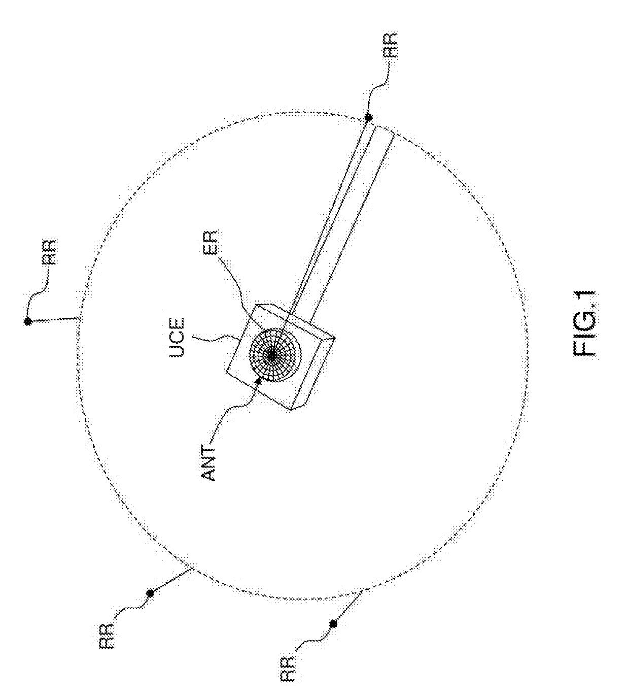
[0037]FIG. 1 shows a system for determining a phase bias in the signal transmitted by at least one of the radiating elements ER of an active antenna ANT on the ground emitting signals into space using a space-division multiple access SDMA method, intended for a set of satellites.

[0038]The system comprises at least three reference receivers RR positioned with respect to the average plane of the active antenna ANT such that their elevation angle is equal to a minimum elevation threshold starting from which the antenna has to be able to communicate with satellites, and at a distance from the antenna that is greater than ten times the maximum wavelength for communication with ...


PUM


Abstract

A method for determining a phase bias in the signal transmitted by at least one of the radiating elements of an active antenna on the ground emitting signals into space using a space-division multiple access SDMA method, implementing a step, for each reference receiver, of comparing, to a threshold, the difference between the value of a measurement of the power received by each reference receiver and the sum, out of the radiating elements of the subset beamforming in the direction of the reference receiver, of the differences between the equivalent isotropically radiated power in the direction of the reference receiver and the free-space path loss of each radiating element of the subset.

Description

CROSS-REFERENCE TO RELATED APPLICATIONS[0001]This application claims priority to foreign French patent application No. FR 1701074, filed on Oct. 16, 2017, the disclosure of which is incorporated by reference in its entirety.FIELD OF THE INVENTION[0002]The invention relates to controlling the emission of signals with spatial division or spatial multiplexing, having the acronym SDMA for “Space-Division Multiple Access”, from an active antenna on the ground into space.BACKGROUND[0003]One difficulty lies in effectively controlling phase and amplitude distortions of antennae and RF chains in substantially “open-loop” operation as, apart from the loss of the signal upon reception at satellites, there is not really a way of monitoring the quality of the emitted signal, and when the loss arises, it is not known a priori how to state which radiating element of the antenna is defective.[0004]These problems are particularly pertinent for ground stations as, with the antenna being in open sky, ...

Claims


Application Information

Patent Timeline
IPC IPC(8): G01S1/02G01S1/04
CPCG01S1/024G01S1/045H01Q3/2635H01Q3/267H04B7/0617H04B7/18517H04B17/12H04B17/318
Inventor CALMETTES, THIBAUDVAUTHERIN, BENO TGREGOIRE, YOANILIOPOULOS, CHRISTELLE
Owner THALES SA
Why Eureka
Try Eureka