
Method for determining the pose of a camera with respect to at least one real object

a technology of real objects and camera poses, applied in the field of methods for determining the pose of cameras with respect to at least one real object, can solve the problem of heavy computational time and achieve the effect of low computational tim

Active Publication Date: 2012-05-17
APPLE INC
View PDF2 Cites 44 Cited by
  • Summary
  • Abstract
  • Description
  • Claims
  • Application Information

AI Technical Summary

Benefits of technology

[0009]It is therefore an object of the present invention to provide a method for determining the pose of a camera with respect to at least one real object which is capable to be computed by a data processing means with rather low computational time.

Problems solved by technology

One of the problems in the field of augmented reality is the determination of the head position and the head orientation of the user by means of a camera that is somehow associated with the user's head.
Another problem may be determining the position and orientation of the camera inside a mobile phone in order to overlay information on the camera image and show the combination of both on the phone's display.
However, since it involves a non-linear minimization problem, it requires heavy computational time.

Method used


Image

  • Method for determining the pose of a camera with respect to at least one real object
  • Method for determining the pose of a camera with respect to at least one real object
  • Method for determining the pose of a camera with respect to at least one real object

Examples


Embodiment Construction

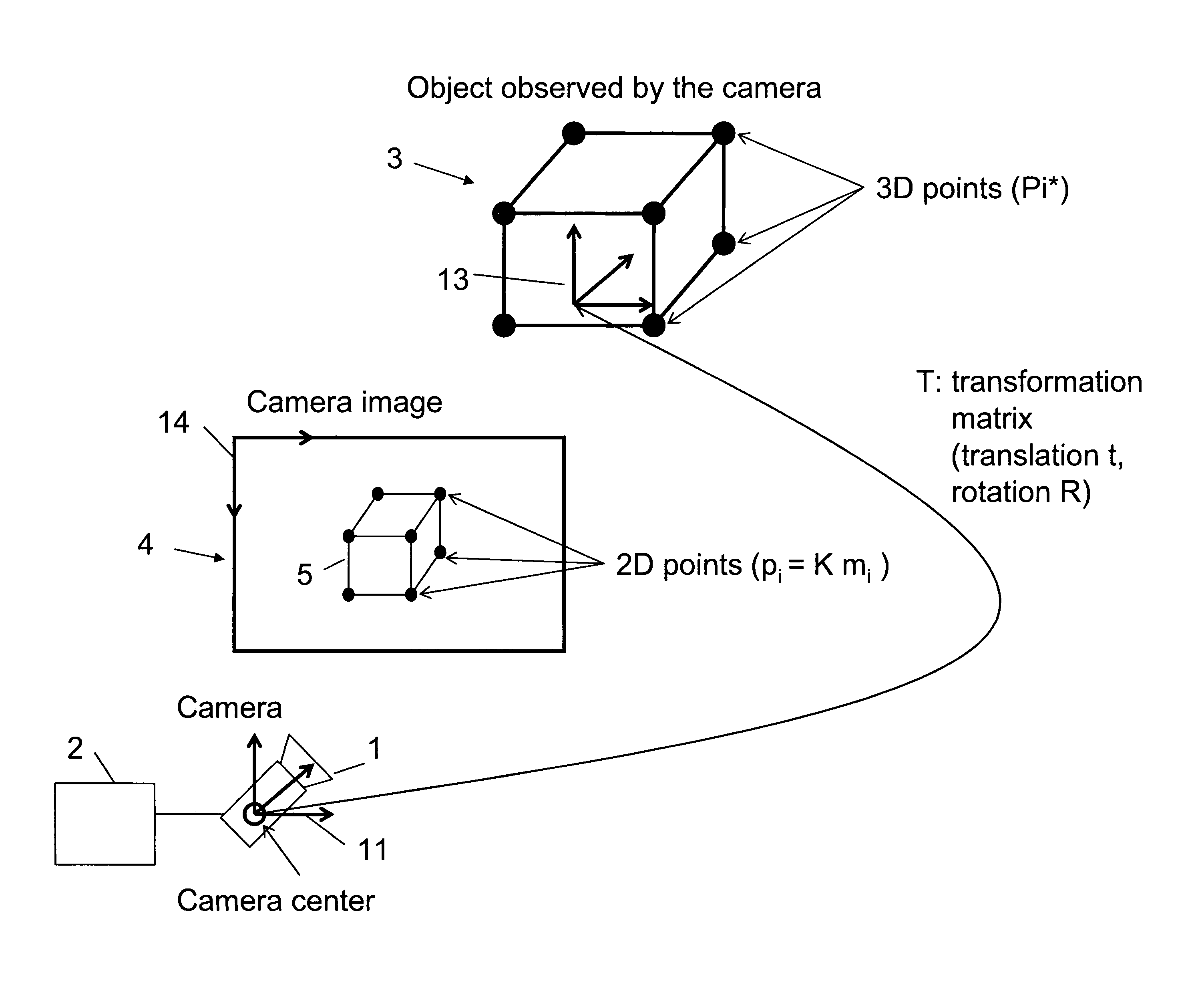
[0034]FIG. 1 shows a schematic visualization of a scene comprising any kind of a real object 3 (in the present example in the form of a cube) comprising 3D points Pi* which is observed by a camera 1. The camera 1 is coupled with a data processing means 2, which may be any kind of computational processor which is appropriate for processing digital images provided by the camera 1. For example, the camera 1 and the processor 2 may be included in the same device, such as a mobile telephone or any other mobile device, or may be incorporated in respective distributed devices coupled in wired or wireless manner. The camera generates one or more camera images 4 displaying a 2-dimensional representation 5 of the real object 3 having 2D points pi. The representation of the object in the image is not restricted to the appearance of the object as a photometric response to the light of the visible spectrum reflected from the object (which corresponds to the standard image acquired by standard co...


PUM


Abstract

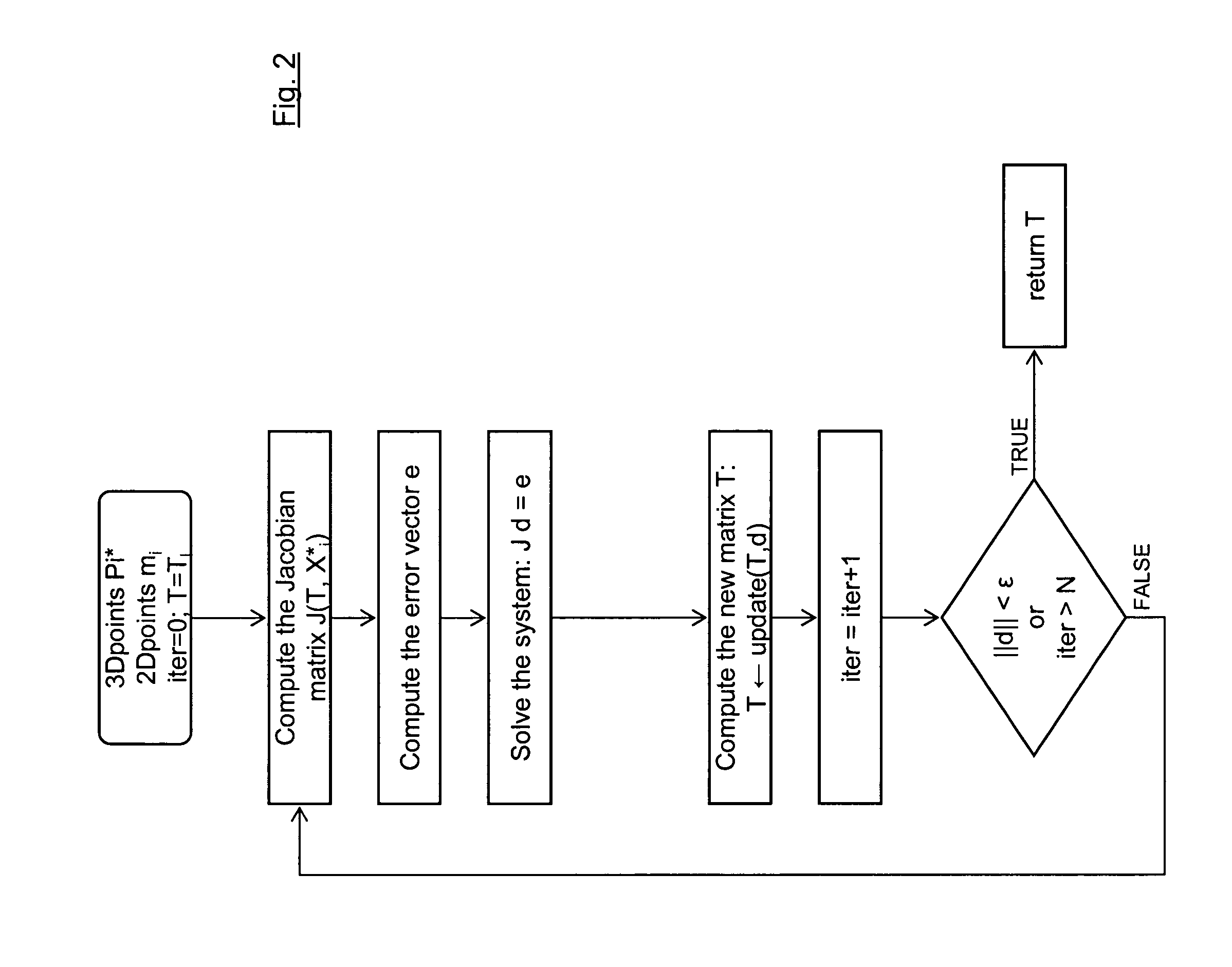
A method for determining the pose of a camera with respect to at least one real object, the method comprises the following steps: operating the camera (1) for capturing a 2-dimensional (or 3-dimensional) image (4) including at least a part of the real object (3), providing a transformation matrix (T) which includes information regarding a correspondence between 3-dimensional points (Pi*) associated with the real object (3) and corresponding 2-dimensional points (or 3-dimensional points) (p,) of the real object (5) as included in the 2-dimensional (or 3-dimensional) image (4), and determining an initial estimate of the transformation matrix (Tl) as an initial basis for an iterative minimization process used for iteratively refining the transformation matrix, determining a Jacobian matrix (J) which includes information regarding the initial estimate of the transformation matrix (Tl) and reference values of 3-dimensional points (Pi*) associated with the real object (3). Further, in the iterative minimization process, in each one of multiple iteration loops determining a respective updated version of the transformation matrix (T) based on a respective previous version of the transformation matrix (T) and based on the Jacobian matrix (J), wherein the Jacobian matrix is not updated during the iterative minimization process, and determining the pose of the camera (1) with respect to the real object (3) using the transformation matrix (T) determined at the end of the iterative minimization process. As a result, the camera pose can be calculated with rather low computational time.

Description

[0001]This application is entitled to the benefit of, and incorporates by reference essential subject matter disclosed in PCT Application No. PCT / EP2009 / 005495 filed on Jul. 29, 2009.BACKGROUND OF THE INVENTION[0002]1. Technical Field[0003]The present invention relates to a method for determining the pose of a camera with respect to at least one real object. A camera is operated for capturing a 2-dimensional image including at least a part of a real object, and in the determination process, the pose of the camera with respect to the real object is determined using correspondences between 3-dimensional points associated with the real object and corresponding 2-dimensional points of the real object in the 2-dimensional image.[0004]2. Background Information[0005]Augmented Reality Systems permit the superposition of computer-generated virtual information with visual impressions of the real environment. To this end, the visual impressions of the real world are mixed with virtual informat...

Claims


Application Information

Patent Timeline
Patent Type & Authority Applications(United States)
IPC IPC(8): H04N13/02H04N7/18
CPCG06T2207/30244G06T7/0046G06T7/75
Inventor BEN HIMANE, MOHAMMED SELIM
Owner APPLE INC
Learn More