Fiber optic connectors, cable assemblies and methods for making the same

a technology cables, applied in the field of fiber optic connectors, cables assemblies and methods for making the same, can solve the problems of difficult manufacturing, difficult to use only a single cable design, and/or high cost, and achieve the effects of convenient installation, simple and reliable, and reliable installation for craftmen and craftsmen

Inactive Publication Date: 2012-05-17
CORNING OPTICAL COMM LLC
View PDF6 Cites 26 Cited by
  • Summary
  • Abstract
  • Description
  • Claims
  • Application Information

AI Technical Summary

Benefits of technology

[0007]The disclosure relates to mechanical splice fiber optic connectors that are reliable, simple, and easy for the craft to install with all types of fiber optic cables. The fiber optic connectors disclosed herein have a holder for attaching a fiber optic cable to a fiber optic connector along with cable assemblies and methods for making the same. A first end of the holder attaches to a portion of a fiber optic connector and a second end of the holder attaches to a fiber optic cable. The fiber optic connectors, cable assemblies and methods disclosed herein are advantageous since they allow the craft to quickly, reliably, and easily attach a robust fiber optic cable to a connector, thereby providing a rugged solution for the craft.

Problems solved by technology

However, conventional connectors require finishing the ferrule endface which is time-consuming and best accomplished in a factory setting with dedicated polishing and inspection equipment.
Manufacturers have attempted to develop mechanical splice connectors that terminate these robust fiber optic cables, but to date the designs require complicated components, numerous components, are difficult to manufacture, useful with only a single cable design, and / or expensive.

Method used


Image

  • Fiber optic connectors, cable assemblies and methods for making the same
  • Fiber optic connectors, cable assemblies and methods for making the same
  • Fiber optic connectors, cable assemblies and methods for making the same

Examples


Embodiment Construction

[0027]Reference is now made to preferred embodiments, examples of which are illustrated in the accompanying drawings. Whenever possible, the same or similar reference numbers and symbols are used throughout the drawings to refer to the same or similar parts.

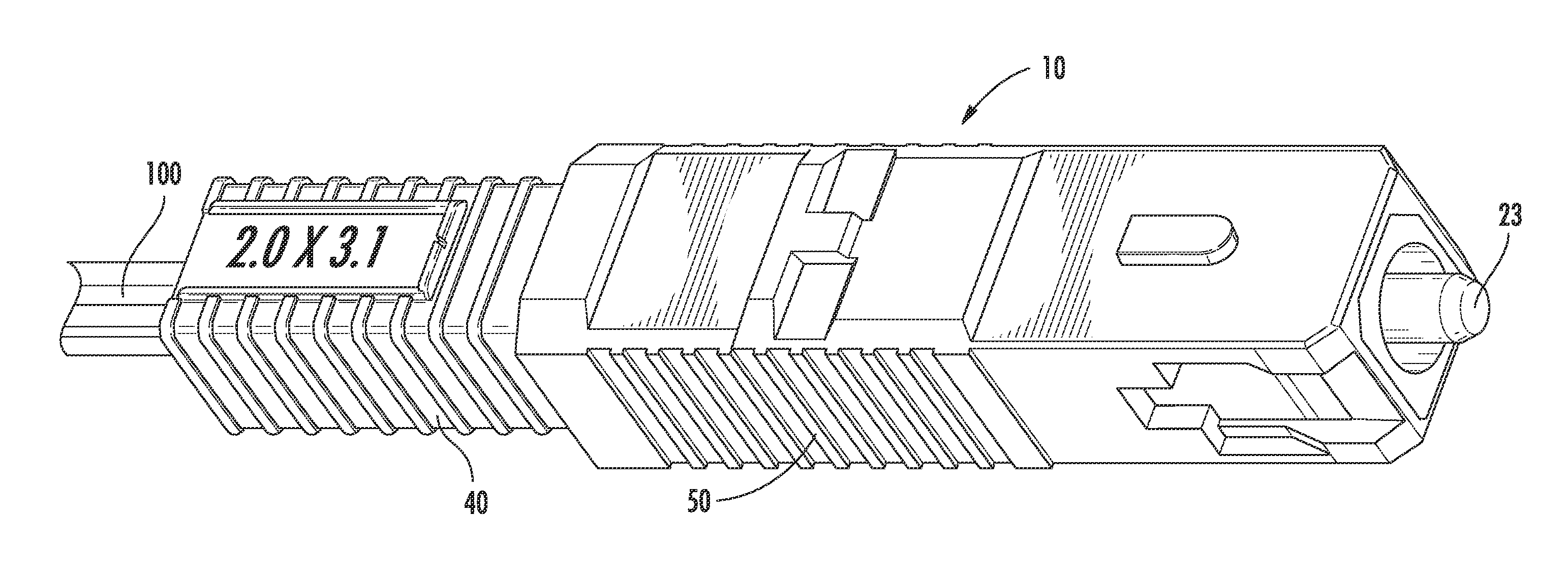
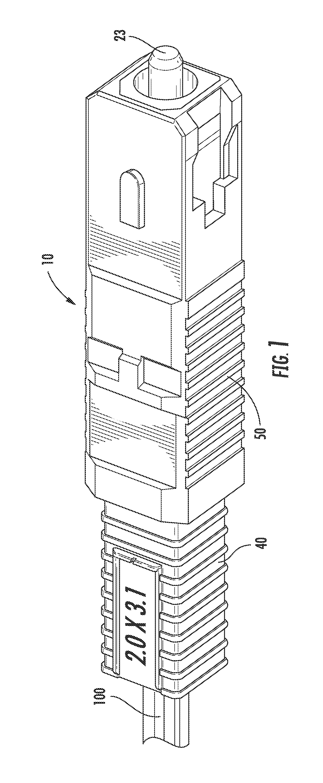
[0028]FIG. 1 is a perspective view of a fiber optic cable assembly 10 (hereinafter cable assembly) having a fiber optic connector 20 (hereinafter connector) attached to a fiber optic cable 100. Cable assembly 10 can include any suitable fiber optic cable and / or type of connector according to the concepts disclosed herein. For instance, the connector type may include SC, LC, MT-RJ, MT, MU, or the like. Additionally, FIGS. 18-22 depict explanatory fiber optic cables suitable for use with the connectors disclosed herein. Generally speaking, fiber optic cables useful with the disclosed connectors generally are robust cable designs with strength members that have an anti-buckling characteristic such as glass-reinforce plastic, fibergl...


PUM

PropertyMeasurementUnit
retention forceaaaaaaaaaa
heightaaaaaaaaaa
heightaaaaaaaaaa

Abstract

Disclosed are fiber optic connectors including a holder for attaching a fiber optic cable to a fiber optic connector along with cable assemblies and methods for making the same. In one embodiment, the holder includes a first and a second cantilevered arm that are squeezed together when a sleeve is placed over the holder. Further, one or more of the cantilevered arm may include a plurality of teeth for “biting” into the cable jacket and providing a suitable fiber optic cable retention force. The fiber optic connectors, cable assemblies and methods disclosed herein are advantageous since they allow the craft to quickly, reliably, and easily attach a robust fiber optic cable to a connector, thereby providing a rugged solution for the craft.

Description

PRIORITY APPLICATION[0001]This application claims the benefit of priority under 35 U.S.C. §365 of International Patent Application Serial No. PCT / US09 / 04421 filed on Jul. 31, 2009 designating the United States of America, the content of which is relied upon and incorporated herein by reference in its entirety.BACKGROUND[0002]1. Field[0003]The present disclosure relates generally to fiber optic connectors, cables assemblies and methods for making the same. Specifically, the disclosure is directed to fiber optic connectors, cable assemblies and methods that use a holder for attaching the fiber optic cable to the connector.[0004]2. Technical Background[0005]Fiber optic communication networks are experiencing explosive growth. In just a few years, the transmission of optical communication signals for voice, video, data, and the like has soared. The future growth of fiber optical networks is necessary because subscribers are still demanding more bandwidth. To accommodate the bandwidth de...

Claims


Application Information

Patent Timeline
Patent Type & Authority Applications(United States)
IPC IPC(8): G02B6/36B32B37/14B32B37/12
CPCG02B6/3806G02B6/3895G02B6/3887G02B6/3846G02B6/3893G02B6/3888
Inventor CASTONGUAY, GUY J.SCHWARTZ, HOWARD C.SUN, JIWEIVO, CHANH C.
Owner CORNING OPTICAL COMM LLC
Why Eureka
Try Eureka