Needle-based medical device and related method

a medical device and needle technology, applied in the field of needle-based medical devices, can solve problems such as patient discomfor

Inactive Publication Date: 2012-05-17
ERSKINE MEDICAL LLC
View PDF3 Cites 63 Cited by
  • Summary
  • Abstract
  • Description
  • Claims
  • Application Information

AI Technical Summary

Benefits of technology

[0006]Further embodiments of a medical device may include a needle having a proximal end, a sharp distal end and a longitudinal axis; a ball bearing movable from a non-blocking position offset from the longitudinal axis of the needle to a blocking position; a needle shield housing, the needle shield housing including: a lumen for accommodating at least part of the needle such that the needle shield housing is slidable at least partially along the longitudinal axis of the needle; an opening for accommodating at least part of the ball bearing in the non-blocking position; and a biasing member for applying a biasing force on the ball bearing, the biasing force including a first component substantially perpendicular to the longitudinal axis of the needle and a second component substantially parallel to the longitudinal axis of the needle, wherein the ball bearing moves by exertion of the biasing force to the blocking position, preventing the needle from emerging from the needle shield housing, in response to a triggering proximal movement of the needle, and wherein the ball bearing is retained in the blocking position by the biasing force.
[0007]The illustrative aspects of the invention are designed to solve one or more of the problems herein described and / or one or more other problems not discussed.

Problems solved by technology

A right angle needle is used because, due to the perpendicular nature of the needle's insertion, any movement of the needle can cause discomfort to the patient.
The shielding of Huber needles pose some technological challenges in that the patient must be provided with a high level of comfort by minimizing the overall height of the device.

Method used


Image

  • Needle-based medical device and related method
  • Needle-based medical device and related method
  • Needle-based medical device and related method

Examples


Embodiment Construction

[0027]As indicated above, aspects of the invention provide embodiments of a needle-based medical device and method of constructing the same.

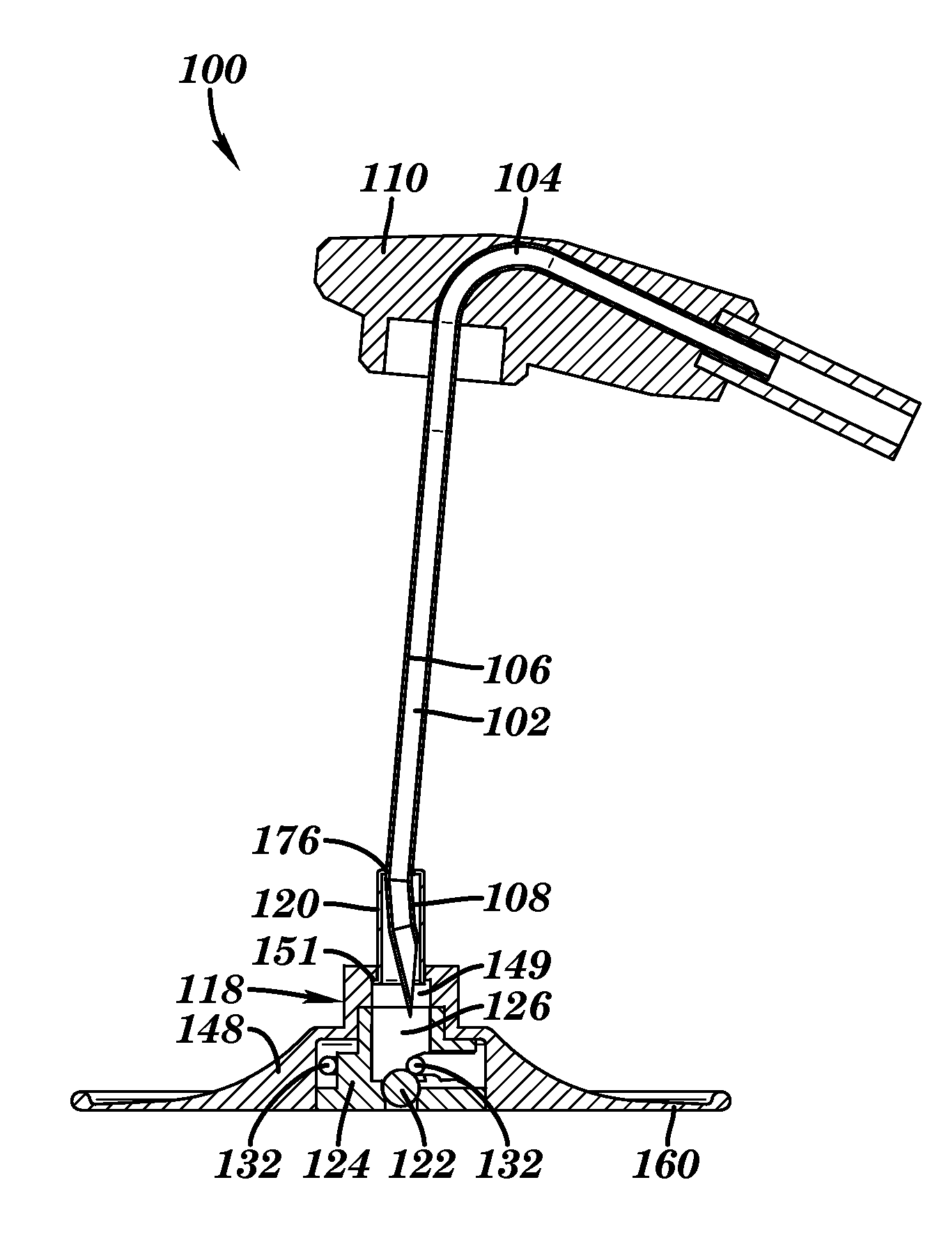
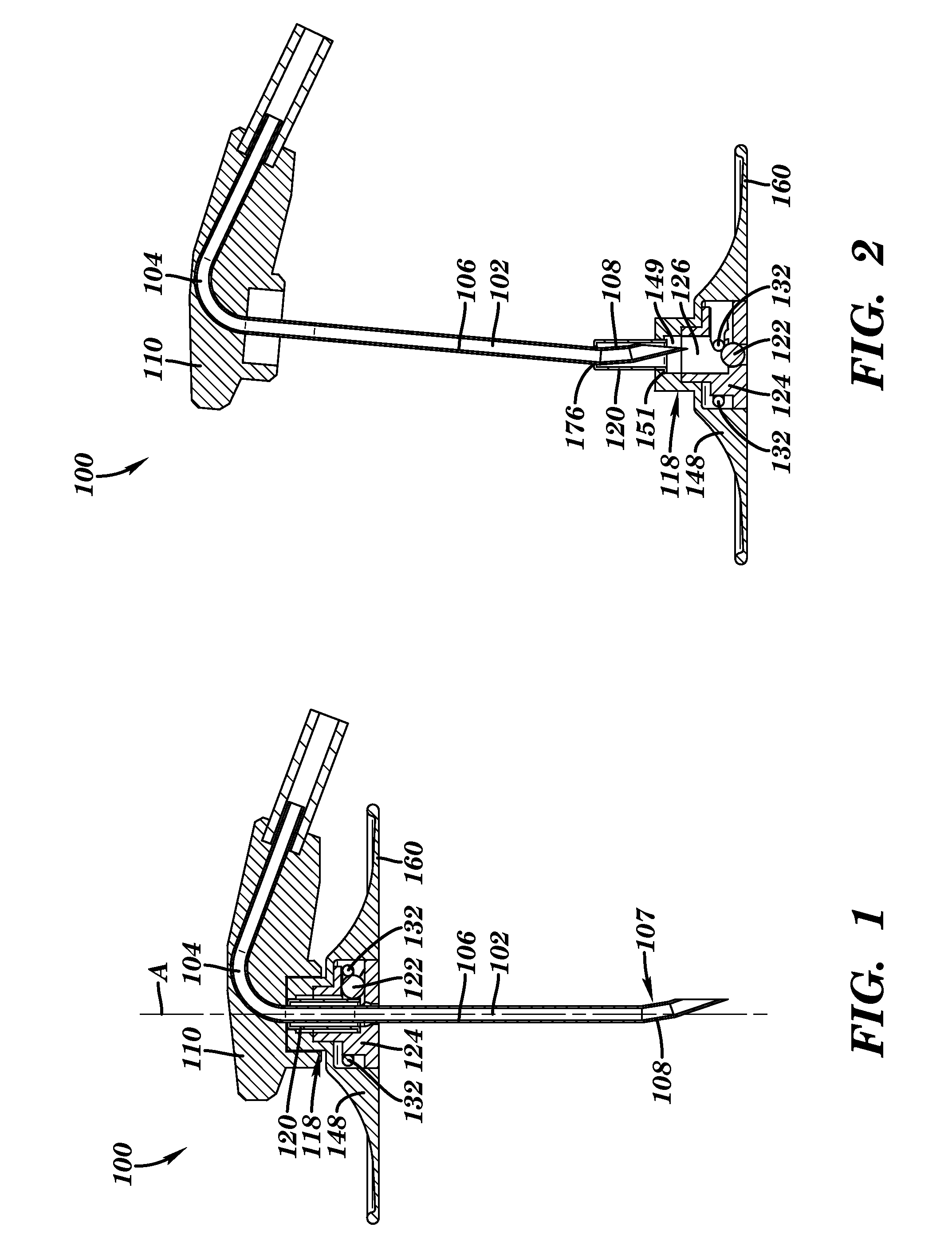
[0028]Referring now to FIGS. 1-2, one embodiment of a needle-based medical device 100 is shown including a needle 102 in the form of a Huber needle. FIG. 1 shows medical device 100 in a non-blocking position of needle 102, and FIG. 2 shows medical device 100 in a blocking position of needle 102, i.e., after use of the needle. Needle 102 includes an approximate right angle 104 to minimize the height of the needle to provide the patient with a high level of comfort during use. Needle 102 includes a proximal end 106, a sharp distal end 108 and a longitudinal axis A (FIG. 1 only). In one embodiment, sharp distal end 108 includes a stopping feature 107 formed by a localized change in the geometry of needle 102. In this embodiment, stopping feature 107 is naturally formed due to the Huber needle tip-forming process where a slight angle is bent into sh...


PUM

PropertyMeasurementUnit
thickaaaaaaaaaa
thickaaaaaaaaaa
biasing forceaaaaaaaaaa

Abstract

A needle-based medical device and a method for constructing it are disclosed. The medical device includes a needle blocking object movable from a non-blocking position offset from the longitudinal axis of the needle to a blocking position; a needle shield housing, the needle shield housing including: a lumen for accommodating at least part of the needle such that the needle shield housing; an opening for accommodating at least part of the needle blocking object; and a biasing member for applying a biasing force on the needle blocking object, the biasing force including a first component substantially perpendicular to the longitudinal axis of the needle and a second component substantially parallel to the longitudinal axis of the needle. The needle blocking object moves by exertion of the biasing force to the blocking position, preventing the needle from emerging from the needle shield housing, in response to a triggering proximal movement of the needle.

Description

TECHNICAL FIELD[0001]The disclosure relates generally to a needle-based medical device, and more particularly, to a needle-based medical device having a needle blocking feature.BACKGROUND ART[0002]Huber needles are used in the medical industry to access implanted ports provided in patients for long-term drug therapy. Huber needles are structured to minimize coring which occurs with a conventional needle when it is inserted into the elastomeric septum and a portion of the septum is cut away. Huber needles typically include a right angle needle which extends from a hub, and some sort of horizontally planar member such as coplanar wings that extend outwardly from the hub. The horizontally planar member is used to grasp and manipulate the Huber needle during accessing of the implanted ports. A right angle needle is used because, due to the perpendicular nature of the needle's insertion, any movement of the needle can cause discomfort to the patient. The right angle needle minimizes the ...

Claims


Application Information

Patent Timeline
Patent Type & Authority Applications(United States)
IPC IPC(8): A61M5/50B23P17/04
CPCA61M5/158A61M5/3273Y10T29/49826A61M2005/325A61M2005/1581
Inventor ERSKINE, TIMOTHY J.
Owner ERSKINE MEDICAL LLC
Why Eureka
Try Eureka