
Pump comprising a moving wall and use of a pump of this type

Inactive Publication Date: 2012-05-17
OTTO BOCK HEALTHCARE IP GMBH & CO KG
View PDF14 Cites 36 Cited by
  • Summary
  • Abstract
  • Description
  • Claims
  • Application Information

AI Technical Summary

Benefits of technology

[0009]In the pump according to the invention, the working stroke by which the fluid, in particular air, is sucked away from a closed-off volume, is brought about by the return force of the elastically deformable material. Previous deformation for reducing the volume of the fluid material takes place by means of a first force acting externally. The pump according to the invention thus makes it possible to have a very uncomplicated and small-volume design, by means of which a low to medium vacuum can be generated.
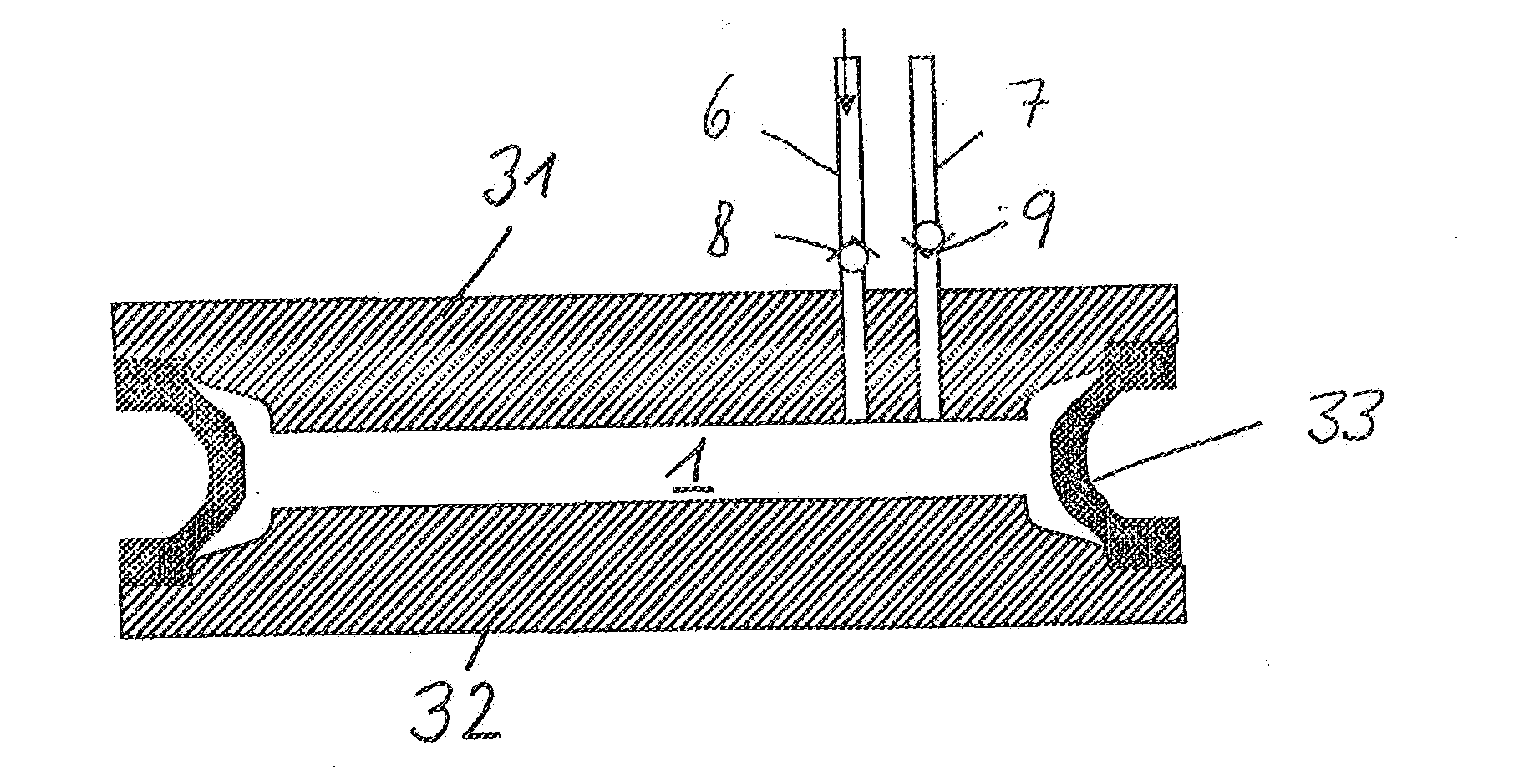
[0010]In a first preferred embodiment of the invention, the wall has two rigid walls lying opposite one another, the elastically deformable material being arranged in the interspace formed by the walls. In this case, the elastically deformable material may be formed by a sealing insert running around the edge and delimiting the fluid volume. This embodiment affords the advantage that the external force can act directly on one of the rigid walls.
[0014]The pump according to the invention can preferably be produced with a preferred large-area extent and with a thickness which is small, as compared with this, and can therefore in many instances be integrated into the structure of a device without difficulty.
[0016]The valves may be arranged on the corresponding narrow sides of the flexible wall, but are preferably also arranged in recesses of one of the pressure elements or of both pressure elements, with the result that flexing actions of the flexible wall are reduced.
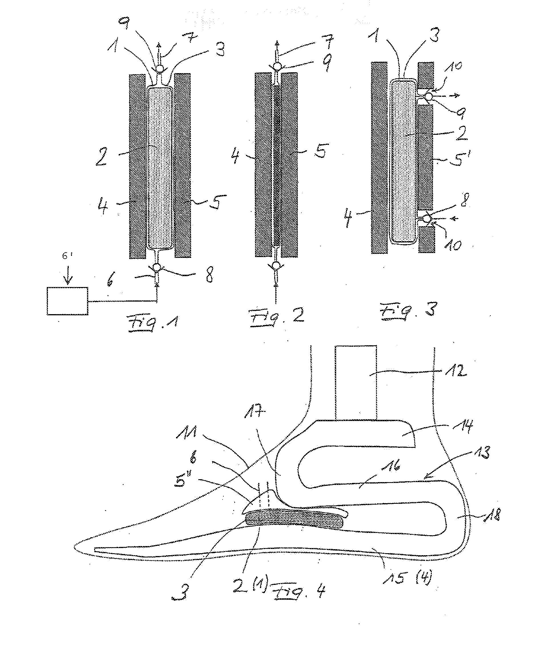
[0018]In a special application, the pump constitutes part of a prosthesis for a lower extremity. Preferably, in this case, the force occurring due to body weight when a patient treads on the ground is utilized as the first force. The pump may be employed, in particular, for the vacuum assistance of a suction well of the prosthesis, in particular for evacuating the interspace between a liner and the prosthesis shank. A preferred place of use for the pump according to the invention is an artificial foot which makes it possible particularly effectively to have the large-area design of the pump perpendicularly to the force flux occurring during load caused by the body weight.

Problems solved by technology

Pumps of this type are relatively bulky particularly because of the return mechanism required.

Method used


Image

  • Pump comprising a moving wall and use of a pump of this type
  • Pump comprising a moving wall and use of a pump of this type
  • Pump comprising a moving wall and use of a pump of this type

Examples


Embodiment Construction

[0028]The pump illustrated in FIG. 1 has a closed fluid volume 1 which is filled virtually completely with an elastic material in the form of an open-pored elastic foam 2. The foam 2 has a substantially large-area extent with a small width. It is surrounded on all sides by a flexible wall 3 which thus has four narrow sides and two large-area sides with large dimensioning, as compared with these. Two large-area pressure elements 4, 5 bear against the large-area sides.

[0029]The flexible wall 3 has on opposite narrow sides a tubular or hose-shaped feed 6 and a tubular or hose-shaped outlet 7. Both the feed 6 and the outlet 7 are provided in each case with a nonreturn valve 8, 9. The feed 6 is in fluid communication with a closed-off volume 6′.

[0030]For the pumping operation, the pressure elements 4, 5 are moved relatively toward one another, as illustrated in FIG. 2. The fluid volume 1 together with the foam 2 contained in it is thereby pressed together, with the result that fluid, pre...


PUM


Abstract

The invention relates to a pump comprising a wall, which forms an enclosed fluid volumetric space and which can be moved by a first force in a direction resulting in a decrease in volume and, after a preceding decrease in volumetric space, can be moved by a second force in a direction resulting in an increase in volume. The pump also comprises an inlet valve, which communicates with an inlet valve, and comprises an outlet valve in an outlet line of the fluid volumetric space. The inventive pump has a compact design due to the fact that it is provided in the form of a vacuum pump whose volumetric space can be decreased by the external first force acting against an elastically deformable material whose restoring force, after the external force ceases, generates the second force acting counter to the generated vacuum.

Description

CROSS-REFERENCE TO RELATED APPLICATION[0001]This application is a continuation of application Ser. No. 11 / 572,863, filed Jan. 29, 2007, pending, which is a 371 of PCT / DE2005 / 001124 filed on Jun. 24, 2005 and published on Feb. 9, 2006 as WO 2006 / 012820, which claims priority to German Patent Application No. 10 2004 036 669.1, filed 28 Jul. 2004, the disclosure of each of which is incorporated, in its entirety, by reference.TECHNICAL FIELD[0002]The invention relates to a pump comprising a wall which forms a closed-off fluid volume and which can be moved by means of a first external force in the direction of a volume reduction and by means of a second force, after a preceding volume reduction, in the direction of a volume increase, and with an inlet valve which communicates with an inlet port and with an outlet valve in an outlet line in the fluid volume.[0003]The invention relates, furthermore, to a use of a pump of this type.BACKGROUND OF THE INVENTION[0004]Pumps of this type are kno...

Claims


Application Information

Patent Timeline
IPC IPC(8): A61F2/80A61F2/78F04B33/00F04B45/02F04B45/04
CPCA61F2002/742A61F2002/747A61F2002/748F04B45/04F04B33/00F04B45/02A61F2002/802A61F2/742A61F2/74A61F2/748
Inventor MOSLER, LUDERHILLMANN, MARTINCARSTENS, RALF
Owner OTTO BOCK HEALTHCARE IP GMBH & CO KG
Learn More