Supercharge Your Innovation With Domain-Expert AI Agents!

Air separation method and apparatus

a separation method and air technology, applied in lighting and heating apparatus, solidification, refrigeration and liquid storage, etc., can solve the problems of limited argon recovery, insufficient reflux of upper sections of the lower pressure column, and limited argon recovery, so as to increase the recoverable argon fraction

Inactive Publication Date: 2012-05-24
PRAXAIR TECH INC
View PDF5 Cites 11 Cited by
  • Summary
  • Abstract
  • Description
  • Claims
  • Application Information

AI Technical Summary

Benefits of technology

The present invention provides a method for separating air by compressing and purifying the air, and then using a higher pressure column and a lower pressure column to produce a crude argon stream and an argon refining column. The method also involves using an intermediate reflux stream to increase the recoverable argon fraction from the air. The technical effect of this invention is to provide a more efficient and effective method for separating air.

Problems solved by technology

In general, argon recovery may be limited by any number of factors.
For instance, argon recovery may be limited by the amount of vapor flow imparted through the base of the low pressure column by way of condensation of the nitrogen-rich vapor overhead produced in the higher pressure column through vaporization of the oxygen-rich liquid produced in the lower pressure column.
Alternatively, the upper sections of the lower pressure column may possess insufficient reflux to adequately maintain a reflux ratio sufficient to trap most of the argon for recovery.
The operation of the argon refining column often reduces the available reflux for the primary double column system given the fact that the crude liquid oxygen is partially vaporized in condensing the crude argon.
Such “liquid pumped” processes often suffer from low argon recovery.
Argon recovery decline is further amplified by the fact that liquid nitrogen and high pressure gaseous nitrogen production will also reduce the available reflux to the lower pressure column.
Unfortunately, the resulting flash gas produced by throttling liquid air into the lower pressure column and / or higher pressure column results in a measureable decline in argon recovery.

Method used


Image

  • Air separation method and apparatus
  • Air separation method and apparatus
  • Air separation method and apparatus

Examples


Embodiment Construction

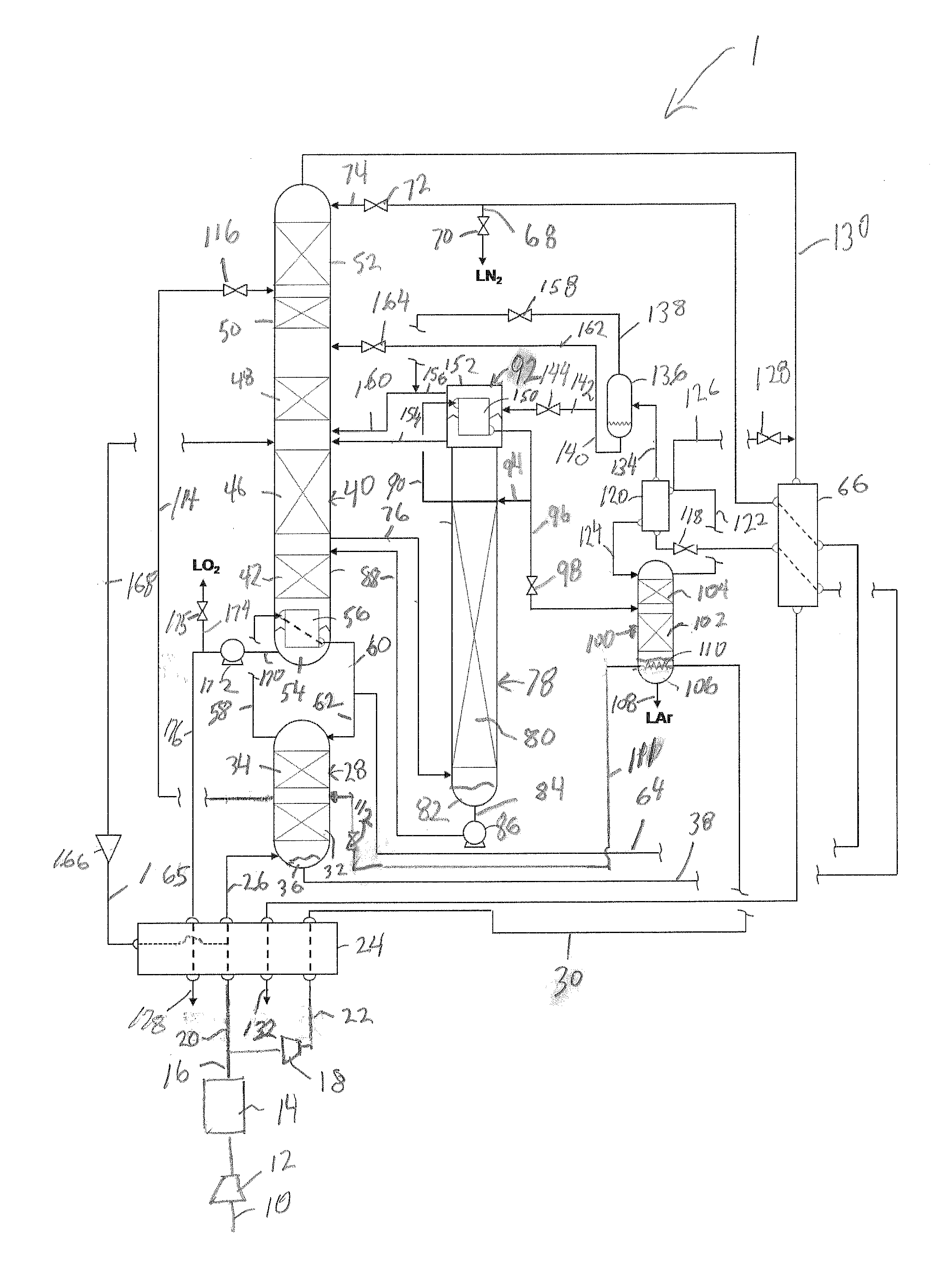
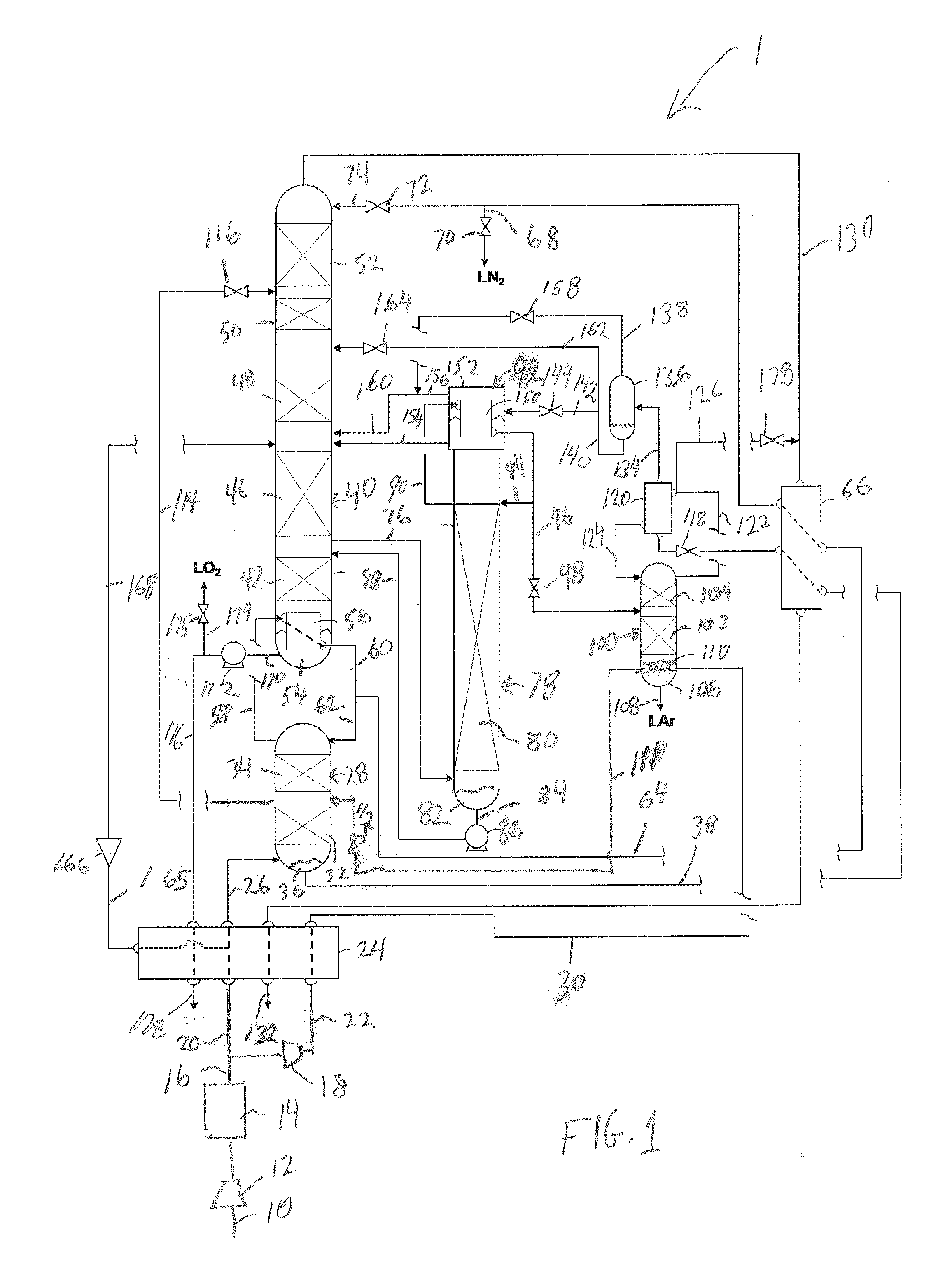
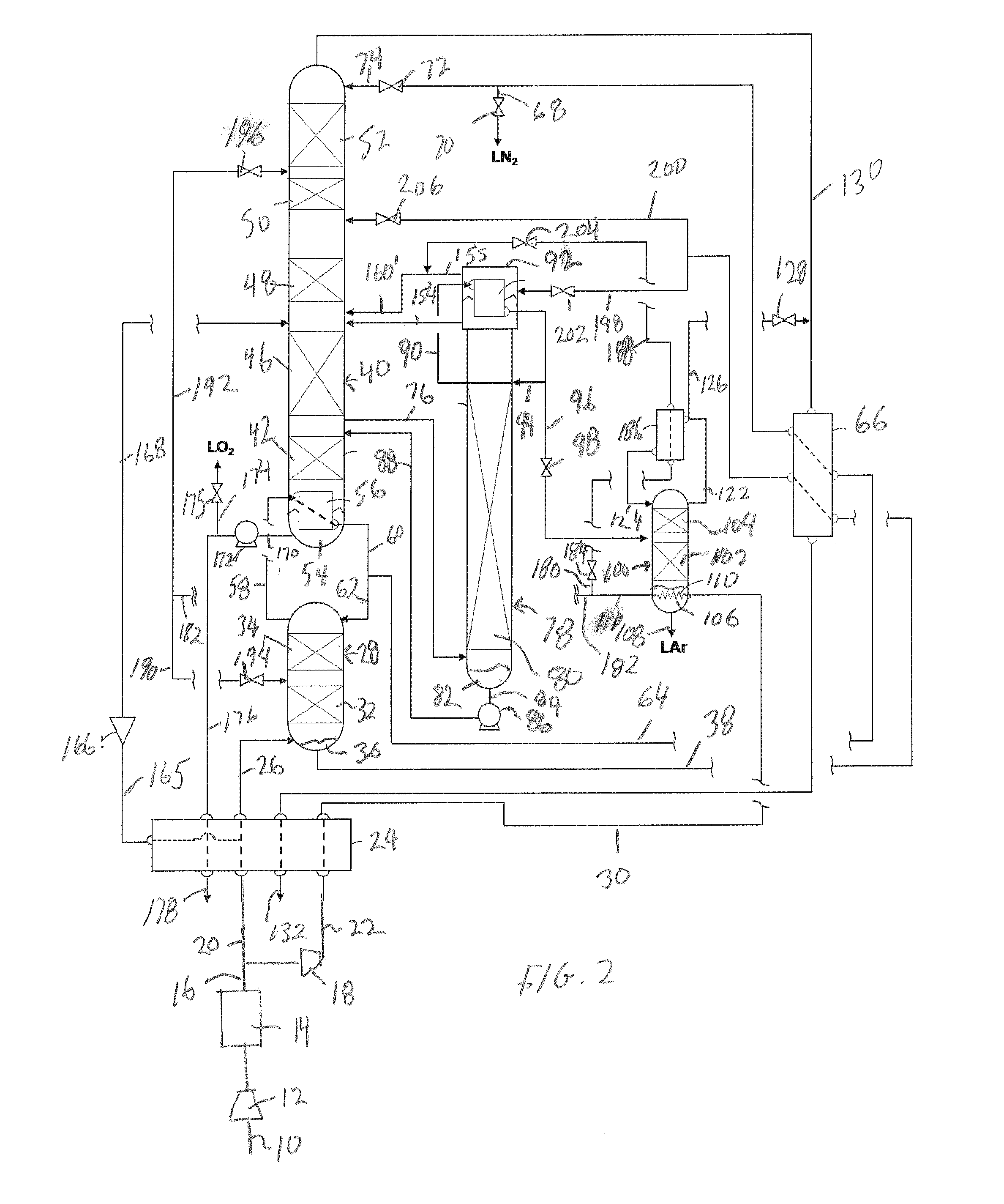
[0029]With reference to FIG. 1, an air separation plant 1 is illustrated that constitutes an apparatus for separating a feed air stream 10 into its respective components. The feed air stream 10 is compressed in a main air compressor 12 and then purified within a purification system 14 connected to main air compressor 12 to produce a compressed and purified air stream 16. A booster compressor 18 is in flow communication with the purification unit 14 such that the compressed and purified air stream 16 is divided into a first compressed air stream 20 and a second compressed air stream 22 having a higher pressure than the first compressed air stream 20. Second compressed air stream 22 constitutes between 25 and 40 percent of the total air entering the plant.

[0030]It is to be pointed out that main compressor 12 and booster compressor 18 can be multi-stage, intercooled integral gear compressors with condensate removal between stages. Both such compressors have, in addition to the intercoo...


PUM


Abstract

A method and apparatus for separating air in which an argon refining column of a distillation column system is reboiled with a liquid air stream. The argon refining column further refines crude argon produced by a crude argon column connected to a lower pressure column of the distillation column system. At least one intermediate reflux stream is formed, at least indirectly, from at least part of the liquid air stream, and is introduced into the lower pressure column at a level thereof above where a crude liquid oxygen column bottoms of a higher pressure column of such system is further refined to increase a liquid to vapor ratio below said level and therefore, argon recovery from the argon refining column.

Description

FIELD OF THE INVENTION[0001]The present invention relates to an air separation method and apparatus in which air is cryogenically rectified in a distillation column system that has a crude argon column connected to a lower pressure column to produce a crude argon stream and an argon refining column connected to the crude argon column to produce an argon product stream. More particularly, the present invention relates to such a method and apparatus in which the argon refining column is reboiled with a liquid air stream that is utilized to produce intermediate reflux to a lower pressure column of the distillation column system to increase argon recovery.BACKGROUND OF THE INVENTION[0002]Air is separated by cryogenic rectification to produce oxygen, nitrogen and argon products. In a typical air separation plant the air is compressed to an elevated pressure (5 to 6 bara), pre-purified within a prepurification unit containing adsorbents and then cooled in a main heat exchanger to cryogeni...

Claims


Application Information

Patent Timeline
Patent Type & Authority Applications(United States)
IPC IPC(8): F25J3/04
CPCF25J3/04303F25J3/0409F25J3/04412F25J3/04678F25J2205/02F25J3/04727F25J2245/58F25J3/04024F25J3/04187F25J3/0423F25J3/04296F25J3/04327F25J3/04654F25J3/04666F25J3/04684F25J3/04721F25J1/0002F25J1/0012
Inventor HOWARD, HENRY EDWARD
Owner PRAXAIR TECH INC
Features
  • R&D
  • Intellectual Property
  • Life Sciences
  • Materials
  • Tech Scout
  • Unparalleled Data Quality
  • Higher Quality Content
  • 60% Fewer Hallucinations
Learn More