Disk brake assembly

Inactive Publication Date: 2012-05-24
GM GLOBAL TECH OPERATIONS LLC
View PDF8 Cites 7 Cited by
  • Summary
  • Abstract
  • Description
  • Claims
  • Application Information

AI Technical Summary

Benefits of technology

[0004]A disk brake assembly in accordance with an exemplary embodiment is provided. The disk brake assembly includes a rotor and a caliper disposed proximate to the rotor. The caliper has first and second body portions and an intermediate portion. The intermediate portion is coupled between the first and second body portions. The first body portion has a first brake pad coupled thereto. The second body portion has a bore extending therein that defines an inner surface. The disk brake assembly further includes a piston disposed within the bore of the second body portion. The piston has an end portion and a tubular body coupled to the end portion. The tubular body has a groove extending circumferentially around the tubular body. The end portion has a second brake pad coupled thereto. The disk brake

Problems solved by technology

However, brake pads in a brake assembly often undesirably contact a rotor after a piston holding one of the brake pads has been depressurized.

Method used


Image

  • Disk brake assembly
  • Disk brake assembly
  • Disk brake assembly

Examples


Embodiment Construction

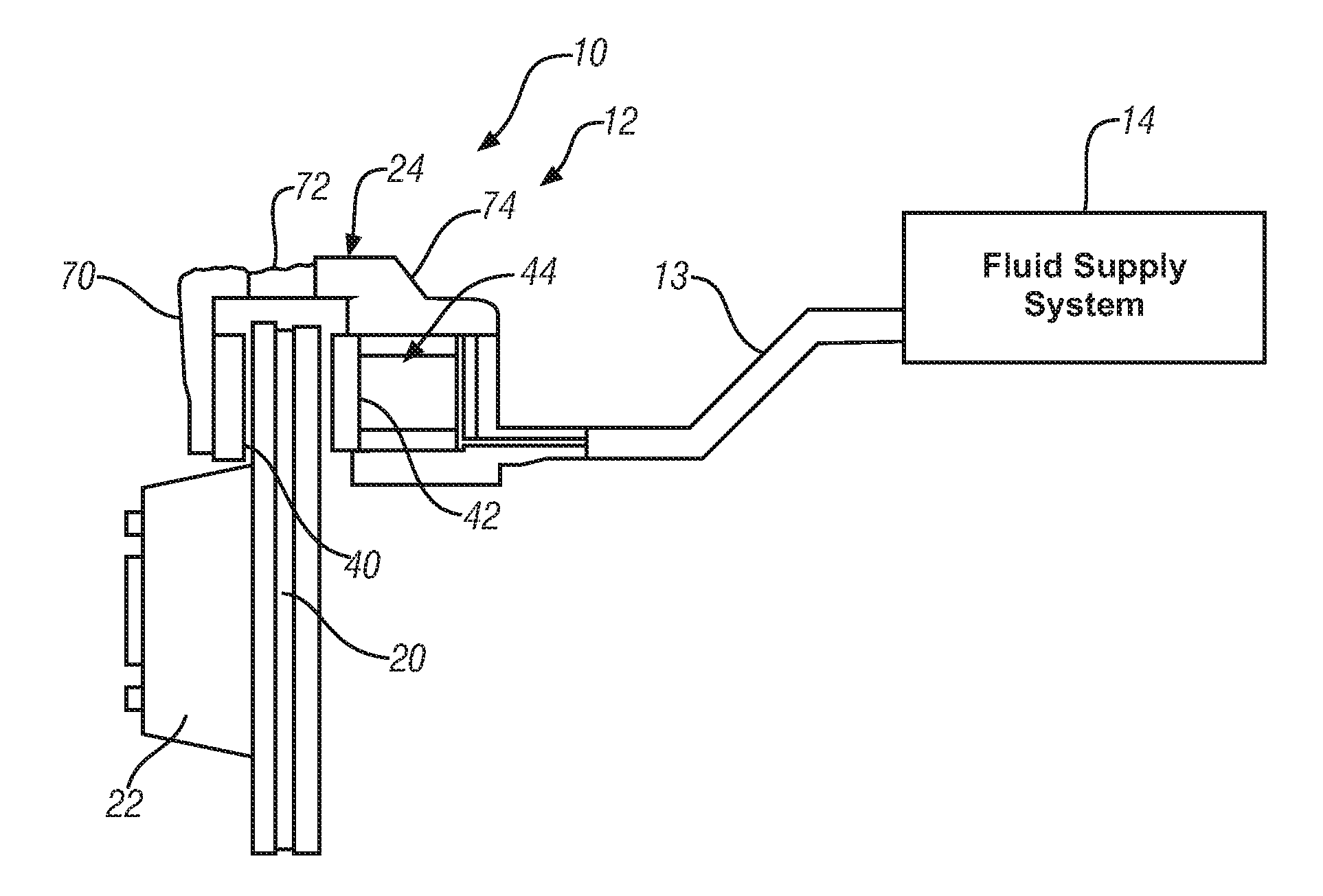
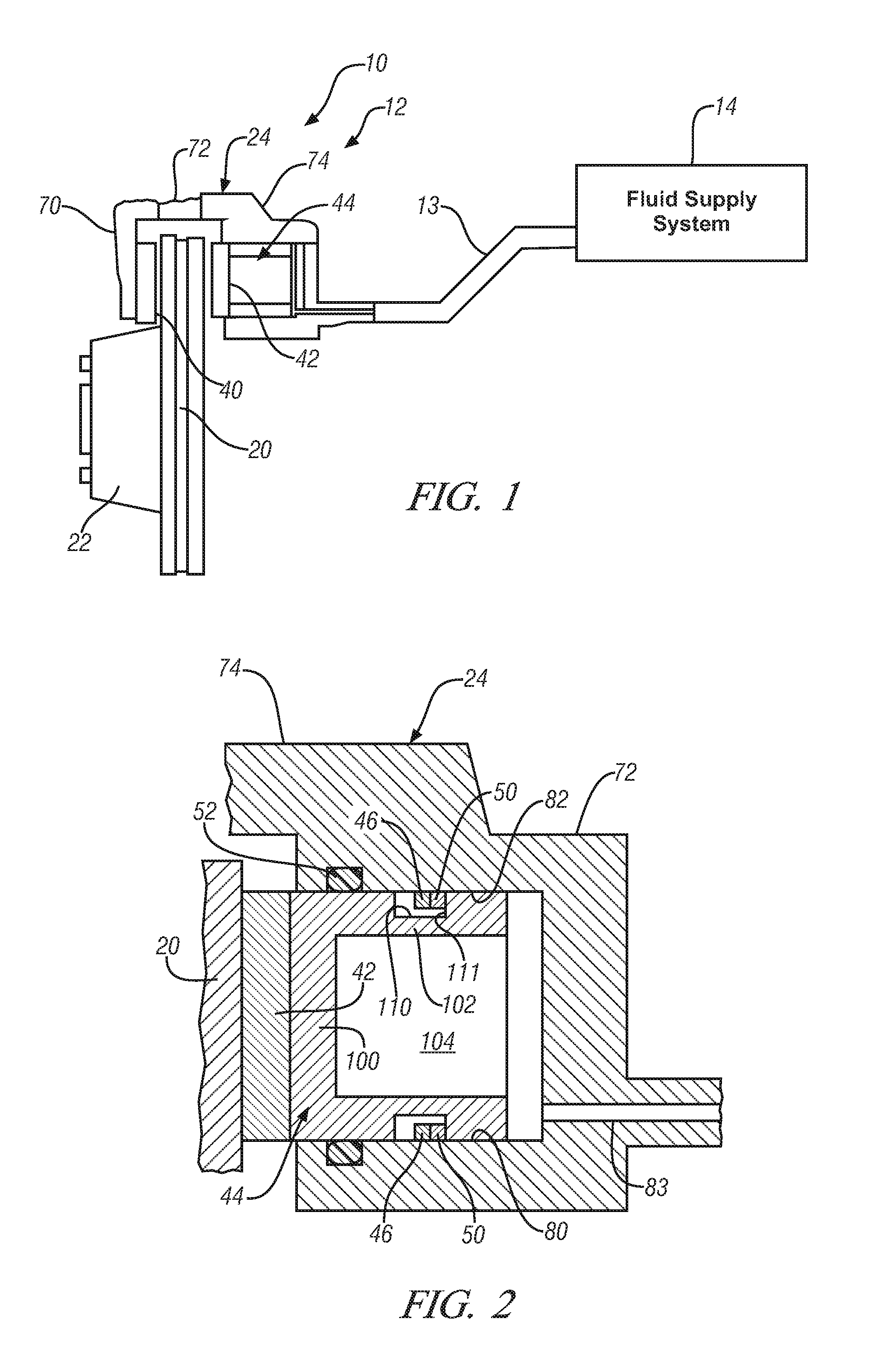
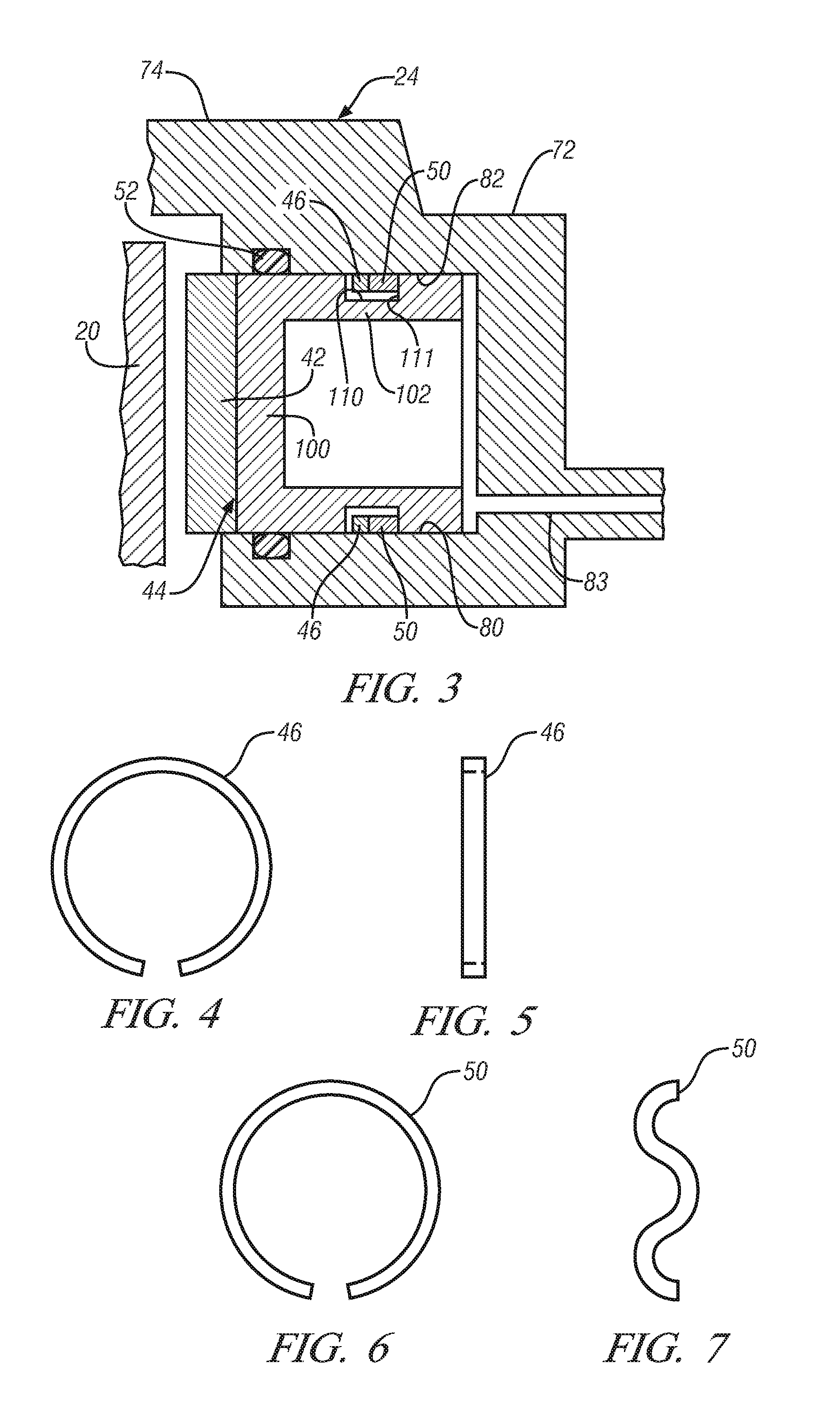
[0018]Referring to FIGS. 1-3, a vehicle 10 having a disk brake assembly 12 in accordance with an exemplary embodiment is provided. The disk brake assembly 12 includes a rotor 20, a hub 22, a caliper 24, brake pads 40, 42, a piston 44, a positioning sleeve member 46, a spring 50, and a seal 52. An advantage of the disk brake assembly 12 is that the assembly can actively move a brake pad away from a rotor to reduce frictional engagement between the brake pad and the rotor.

[0019]The caliper 24 holds the brake pads 40, 42 thereon and is disposed adjacent to the rotor 20. The caliper 24 includes body portions 70, 72 and an intermediate portion 74 coupled between the body portions 70, 72. The body portion 70 has the brake pad 40 disposed thereon, and the body portion 72 has the brake pad 42 disposed thereon. The body portion 72 includes a bore 80 that extends therein for receiving the piston 44 therein. The body portion 72 further includes an inner surface 82 defined by the bore 80. Also,...


PUM


Abstract

A disk brake assembly having a rotor and a caliper is provided. The caliper has first and second body portions and an intermediate portion coupled between the body portions. The first body portion has a first brake pad coupled thereto. The second body portion has a bore extending therein that defines an inner surface. The assembly further includes a piston disposed within the bore. The piston has an end portion and a tubular body coupled to the end portion. The end portion has a second brake pad coupled thereto. The assembly further includes a positioning sleeve member disposed on a portion of the inner surface within a portion of the groove. The assembly further includes a spring disposed in the groove that moves the piston and the second brake pad away from the rotor in response to a decreased fluid pressure in the piston.

Description

FIELD OF THE INVENTION[0001]The present application is directed to a disk brake assembly.BACKGROUND[0002]Brake assemblies have been developed. However, brake pads in a brake assembly often undesirably contact a rotor after a piston holding one of the brake pads has been depressurized.[0003]Accordingly, it is desirable to provide an improved disk brake assembly.SUMMARY OF THE INVENTION[0004]A disk brake assembly in accordance with an exemplary embodiment is provided. The disk brake assembly includes a rotor and a caliper disposed proximate to the rotor. The caliper has first and second body portions and an intermediate portion. The intermediate portion is coupled between the first and second body portions. The first body portion has a first brake pad coupled thereto. The second body portion has a bore extending therein that defines an inner surface. The disk brake assembly further includes a piston disposed within the bore of the second body portion. The piston has an end portion and...

Claims


Application Information

Patent Timeline
IPC IPC(8): F16D55/226F16D65/20
CPCF16D65/18F16D2121/04F16D65/54
Inventor WONG, ALBERT C.WONG, TOM CHEUK-IN
Owner GM GLOBAL TECH OPERATIONS LLC
Why Eureka
Try Eureka