Positioning fixture assembly

a technology of positioning fixture and assembly, which is applied in the direction of manufacturing tools, work holders, metal-working machine components, etc., can solve the problem that the positioning fixture assembly cannot be easily adjusted to provide a suitable angl

Inactive Publication Date: 2012-05-24
SHENZHEN FUTAIHONG PRECISION IND CO LTD +1
View PDF2 Cites 0 Cited by
  • Summary
  • Abstract
  • Description
  • Claims
  • Application Information

AI Technical Summary

Benefits of technology

[0004]Positioning fixture assemblies are widely used in manufacturing or assembling processes to hold or support workpieces. Conventional positioning fixture assemblies define a receiving space for securing a workpiece in place to conveniently cut or grind. When the workpiece has more than one surface to be machined, the positioning fixture assembly cannot easily be adjusted to provide a suitable angle for working on the workpiece

Problems solved by technology

When the workpiece has more than one surface to be machined, the positioning fixture assembly cannot easily be adjusted to provide a suitable angle for working on the workpiece

Method used


Image

  • Positioning fixture assembly
  • Positioning fixture assembly
  • Positioning fixture assembly

Examples


Embodiment Construction

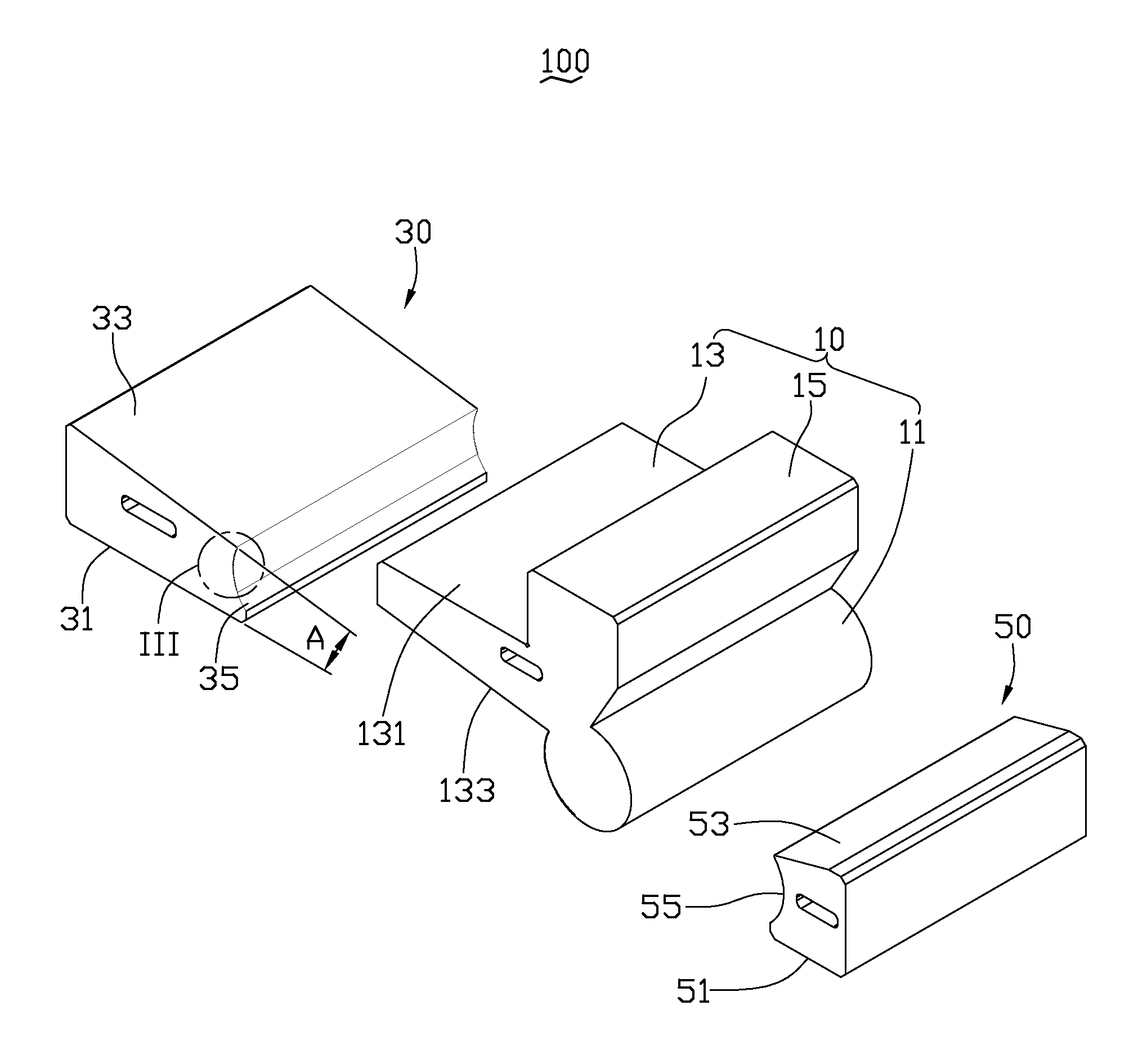
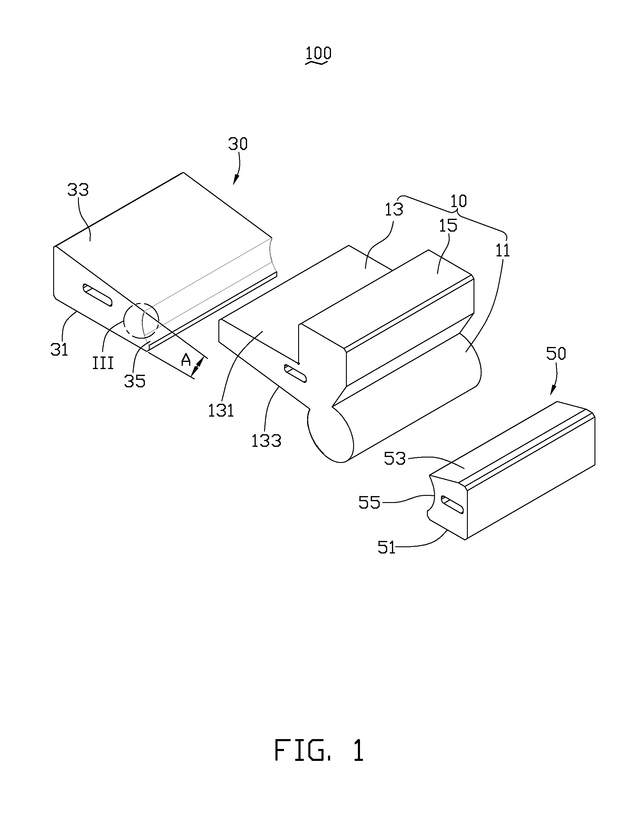
[0013]The disclosure is illustrated by way of example and not by way of limitation in the accompanying drawings. It should be noted that references to “an” or “one” embodiment in this disclosure are not necessarily to the same embodiment, and such references can include the meaning of “at least one” embodiment where the context permits.

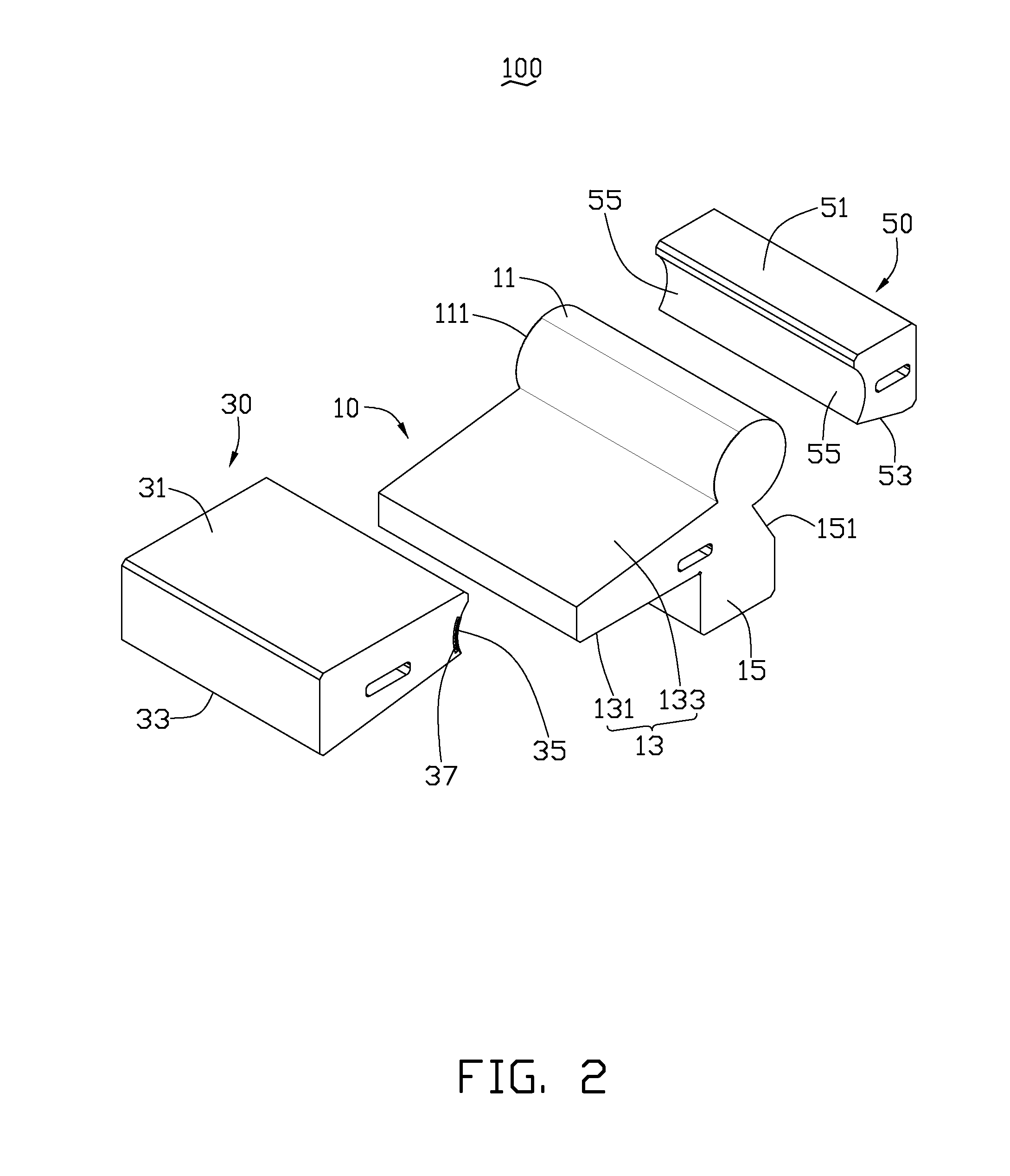
[0014]FIG. 1 and FIG. 2 illustrate a positioning fixture assembly 100 to support a workpiece (not shown) during either a machining operation or other process. The positioning fixture assembly 100 includes a support member 10, a first clamping member 30, and a second clamping member 50. The first clamping member 30 and the second clamping member 50 are attached to a vice clamp (not shown) for clamping the support member 10. The support member 10 is used to load the workpiece and is rotatably retained between the first and the second clamping members 30 and 50.

[0015]The support member 10 includes a connecting portion 11, a support portion 13, and a flan...


PUM


Abstract

A positioning fixture assembly includes a support member, a first clamping member, and a second clamping member. The support member includes a substantially cylindrical connecting portion and a supporting portion. A number of receiving grooves are defined in the connecting portion. The supporting portion includes a first surface. The first clamping member defines a first receiving slot and includes a first mounting surface and a first resisting surface. At least one projection projects from the bottom surface of the receiving slot. The connecting portion is received in the first and second receiving slots and is clamped by the first and second clamping members. The at least one projection is selectively received in the receiving grooves so that an angle is defined between the first surface and the first mounting surface.

Description

BACKGROUND[0001]1. Technical Field[0002]The disclosure generally relates to positioning fixture assemblies and, particularly, to an adjustable positioning fixture assembly.[0003]2. Description of Related Art[0004]Positioning fixture assemblies are widely used in manufacturing or assembling processes to hold or support workpieces. Conventional positioning fixture assemblies define a receiving space for securing a workpiece in place to conveniently cut or grind. When the workpiece has more than one surface to be machined, the positioning fixture assembly cannot easily be adjusted to provide a suitable angle for working on the workpiece[0005]Therefore, there is room for improvement within the art.BRIEF DESCRIPTION OF THE DRAWINGS[0006]Many aspects of the exemplary positioning fixture assembly can be better understood with reference to the following drawings. The components in the drawings are not necessarily drawn to scale, the emphasis instead being placed upon clearly illustrating th...

Claims


Application Information

Patent Timeline
Patent Type & Authority Applications(United States)
IPC IPC(8): B25B11/00
CPCB23Q3/04
Inventor HUANG, DA-HAI
Owner SHENZHEN FUTAIHONG PRECISION IND CO LTD
Why Eureka
Try Eureka