
Automatic accommodative spectacles using a scene analyzer and focusing elements

a technology of scene analyzer and focusing element, applied in the field of automatic accommodative spectacles, can solve the problems of only being implanted in the patient's eye after a-iol, unifocal correction devices cannot adapt to such changes, and patients' refractive errors can change overtime, so as to improve the location of the patient's fixation roi

Active Publication Date: 2012-05-24
LITEMAZE TECH SHENZHEN CO LTD
View PDF2 Cites 42 Cited by
  • Summary
  • Abstract
  • Description
  • Claims
  • Application Information

AI Technical Summary

Benefits of technology

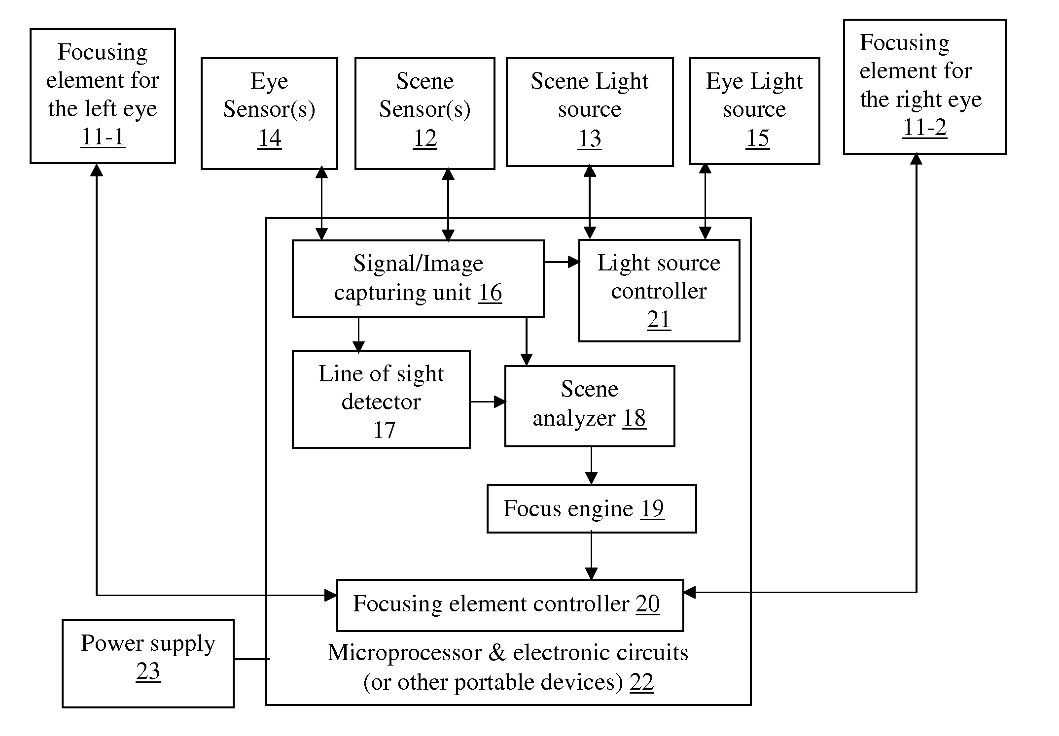
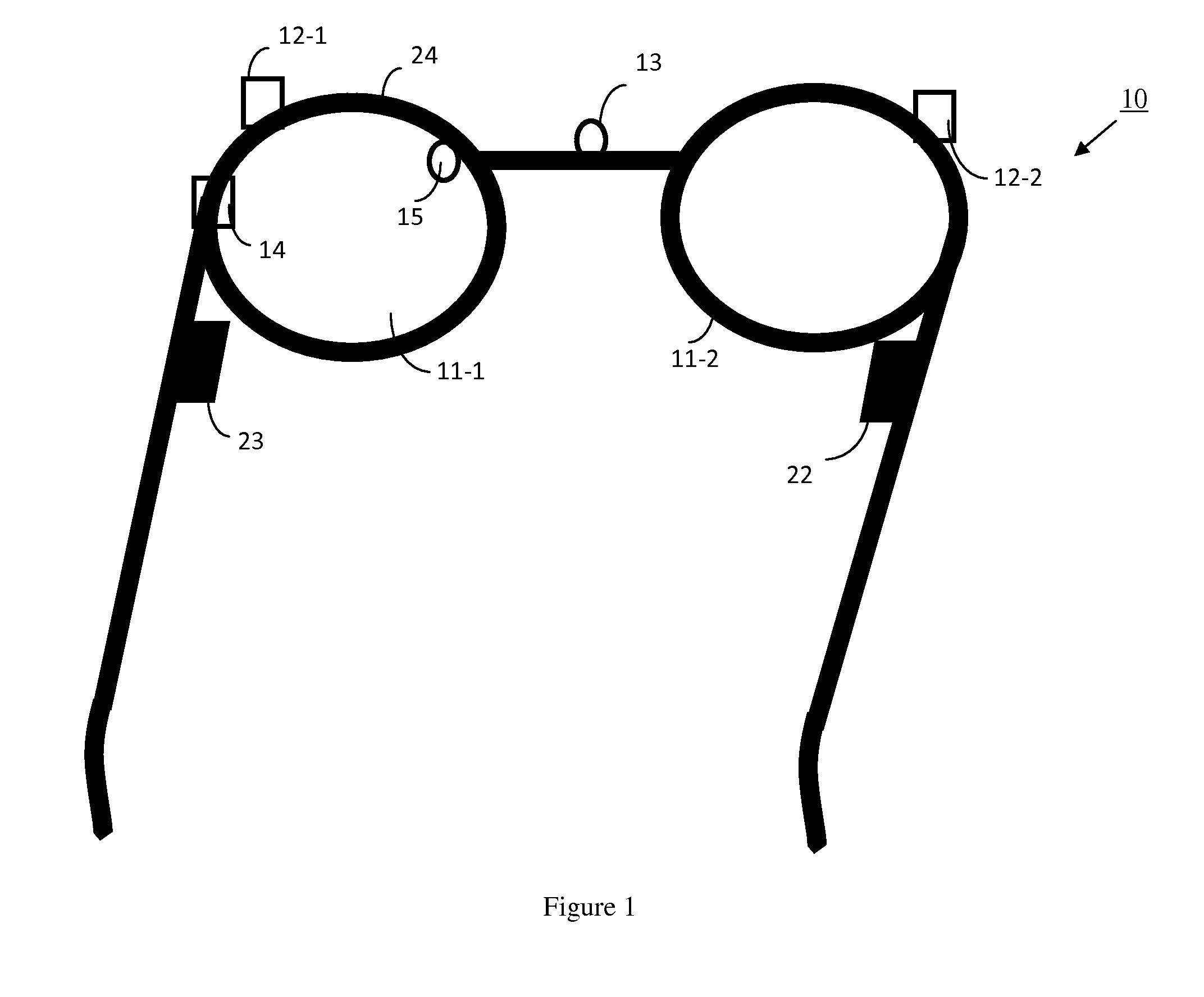
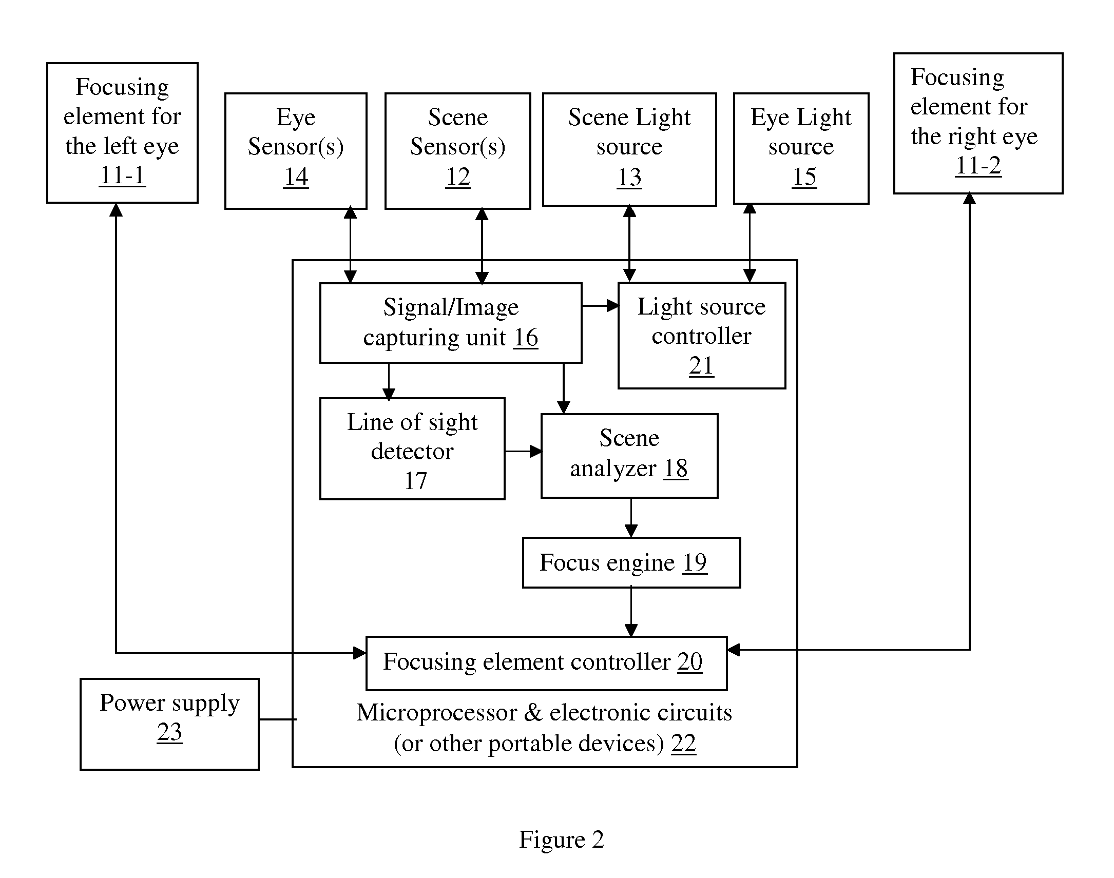
[0010]To achieve these and other advantages and in accordance with the purpose of the present invention, as embodied and broadly described, the present invention provides an automatic accommodative spectacle device for use by a patient (user), which includes: a spectacle frame; one or more sensors that capture the scene in the user's field of view; a scene analyzer that analyzes the scene signals captured by the sensors to determine the 3-dimensional location of the ROI; a focus engine for determining optimum powers for the focusing elements based on the location of the ROI; and a focusing elements controller connected to the focusing elements and the focus engine for controlling optical powers of the focusing elements based on the optimum powers for the focusing elements determined by the focus engine.
[0011]Multiple types of sensors, such as CCD / CMOS grayscale or color image sensors, depth image sensors based on time-of-flight or structured light technology, and so on, can be used to provide scene signals to the scene analyzer. How the scene analyzer works depends on what type of signals / images are generated by the sensors. But its fundamental goal is to find the ROI in the scene and compute the distances between the user's eyes and the ROI. The later may either be directly supplied by the sensors, or computed in the scene analyzer. One or more additional optional sensor can be used to monitor one eye of the user and a optional line of sight detector can determine its line of sight, which in turn is used by the scene analyzer to better locate the patient's fixation ROI.

Problems solved by technology

Unfortunately, patients' refractive errors can change overtime and unifocal correction devices cannot adapt to such changes.
But A-IOL can only be implanted in patients' eyes after cataract surgeries.
They usually require the patients to use different regions of the devices or look at targets in specific fashions, putting significant constraints on how patients look at their targets of interest.
However, in these proposals, how to determine the needed optical power of the lenses are not specified.
Such devices can be useful for patients in certain cases where the viewing targets are stationary or changing infrequently, but are not practical for general usage.

Method used


Image

  • Automatic accommodative spectacles using a scene analyzer and focusing elements
  • Automatic accommodative spectacles using a scene analyzer and focusing elements
  • Automatic accommodative spectacles using a scene analyzer and focusing elements

Examples


Embodiment Construction

[0019]A co-pending U.S. patent application by the same inventors, U.S. patent application Ser. No. 12 / 916,508, filed Oct. 30, 2010, is herein incorporated by reference in its entirety. This co-pending application describes automatic accommodative spectacles that use sensors to monitor the patient's lines of sight to determine his / her fixation ROI. In real-time, the associated necessary optical power adjustments are estimated, and focusing elements are adjusted accordingly. This method is adequate for the majority of the patients whose two eyes can align properly and the lines of sight of both eyes can be monitored. However, for patients whose two eyes cannot properly align with each other due to strabismus or other ocular conditions, or patients whose two lines of sight cannot be detected properly at the same time, an alternative approach is needed.

[0020]The present disclosure describes a spectacle device that automatically focuses on the fixation ROI of the patient (user) using sce...


PUM


Abstract

A pair of spectacles that can automatically change its power so that a fixation region of interest (ROI) of the user is always in focus. The automatic accommodative spectacle device includes focusing elements, scene sensors, scene analyzer, focus engine, focusing element controller, and power supply. The scene analyzer determines the fixation ROI in the scene by analyzing the scene images. The fixation ROI is used to determine powers for the focusing elements in order to bring the fixation ROI into focus. The focusing element controller carries out the needed optical power adjustment to apply to the focusing elements. Optional light sources may be provided to the scene sensors. Additional optional eye sensor(s), eye light source and line of sight detector can be used to help the scene analyzer extract the fixation ROI.

Description

BACKGROUND OF THE INVENTION[0001]1. Field of the Invention[0002]This invention relates to spectacles. In particular, it relates to automatic accommodative spectacles that use a scene analyzer to determine a patient's region of interest (ROI or fixation ROI) in the scene of the field of view of the patient (user) and automatically adjust the optical power of focusing elements on the spectacles to help him / her remain focused on the fixation ROI.[0003]2. Description of the Related Art[0004]Spectacles and contact lenses are commonly used optical devices to correct refractive errors, such as myopia (nearsightedness) and hyperopia (farsightedness). Most prescribed spectacles and contact lenses are unifocal that have one fixed optical power. Unfortunately, patients' refractive errors can change overtime and unifocal correction devices cannot adapt to such changes. In addition, patients with presbyopia, that is, people whose eyes cannot adequately focus on nearby objects due to aging, need ...

Claims


Application Information

Patent Timeline
Patent Type & Authority Applications(United States)
IPC IPC(8): G02C11/00G02C7/06
CPCG02B7/365G02C7/081G02C11/10G02C7/061G02B15/14
Inventor TIAN, YIBINDUONG, THANG
Owner LITEMAZE TECH SHENZHEN CO LTD
Learn More