Rotational Milling Chamber

Inactive Publication Date: 2012-05-31
KEJTERPILLAR R L +1
View PDF2 Cites 0 Cited by
  • Summary
  • Abstract
  • Description
  • Claims
  • Application Information

AI Technical Summary

Problems solved by technology

During milling operations, picks may wear or break requiring maintenance of the drum before a job's completion.
Such repairs delay projects and reduce profitability.

Method used


Image

  • Rotational Milling Chamber
  • Rotational Milling Chamber
  • Rotational Milling Chamber

Examples


Embodiment Construction

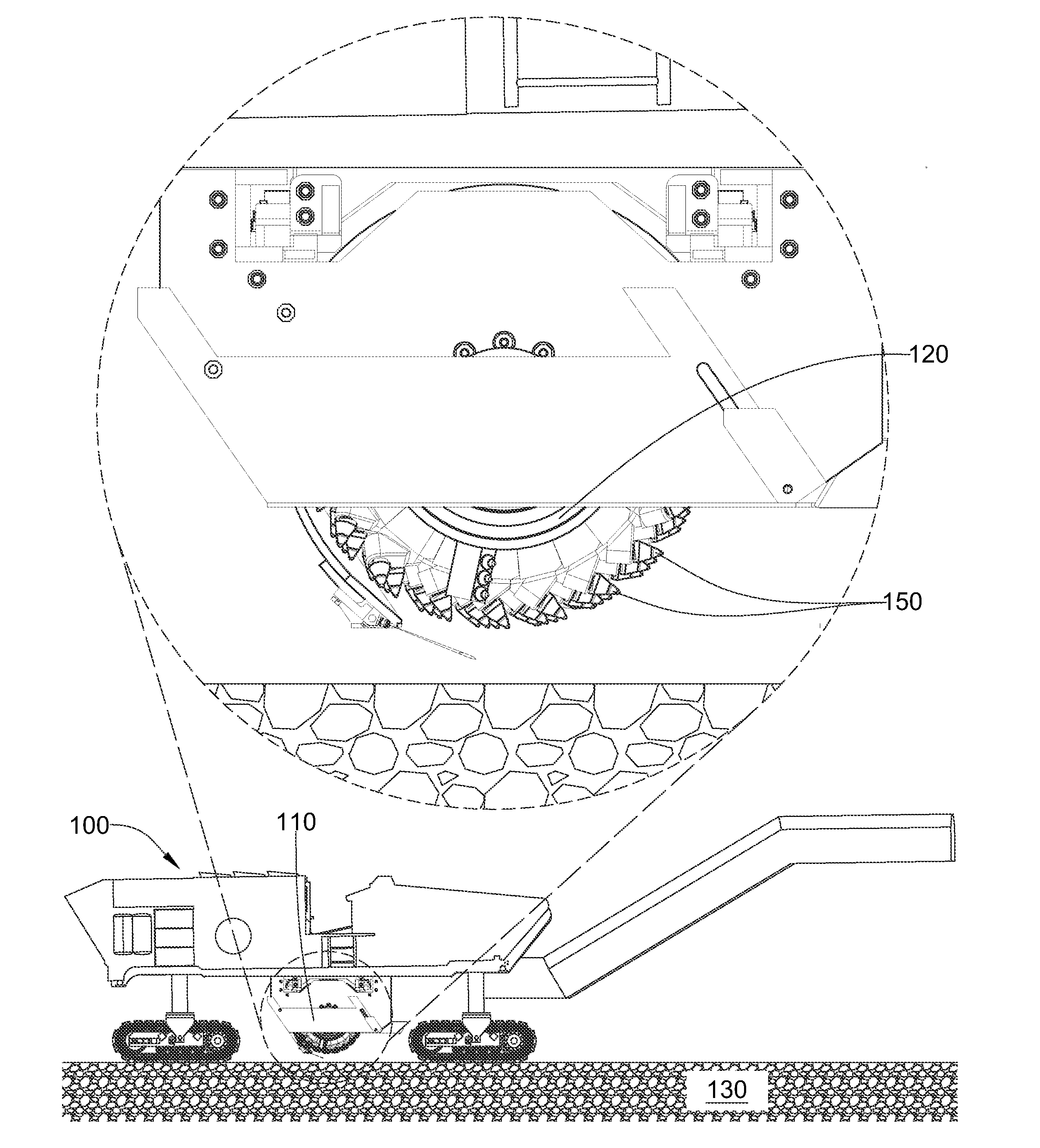
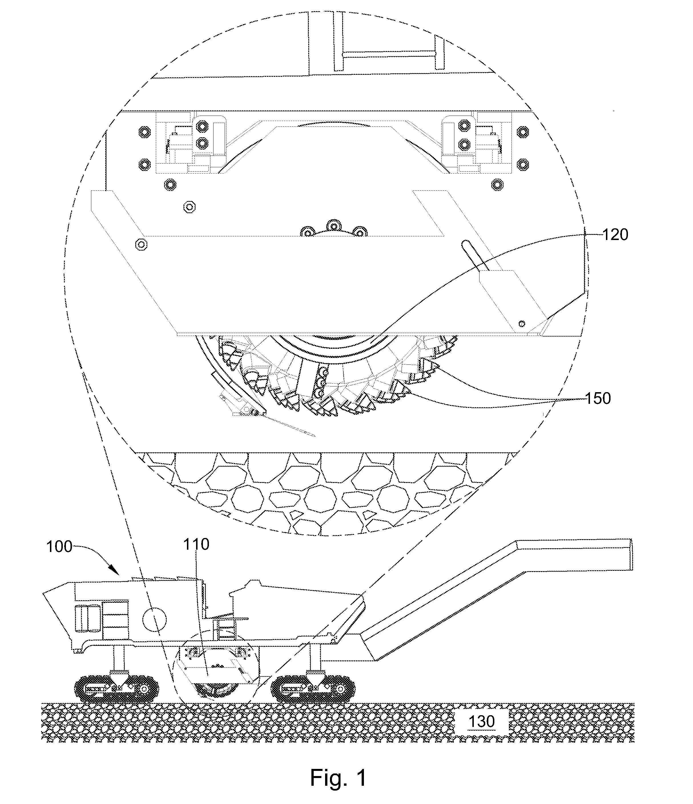
[0033]FIG. 1 is an orthogonal diagram of an embodiment of a milling machine 100 comprising a milling chamber 110. The milling chamber 110 may comprise a rotary drum assembly 120, a moldboard, front plate, and side plates. The milling machine 100 may be an asphalt planar used to degrade man-made formations 130 such as pavement prior to placement of a new layer of pavement. The milling chamber 110 may be attached to the underside of the milling machine 100. The rotary drum assembly 120 may comprise a plurality of cutting elements 150. A holder, such as a block welded or bolted to the rotary drum assembly 120 may hold the cutting elements 150 at an angle offset from a direction of rotation of the drum, such that the cutting elements 150 engage the formation 130 at a preferential angle.

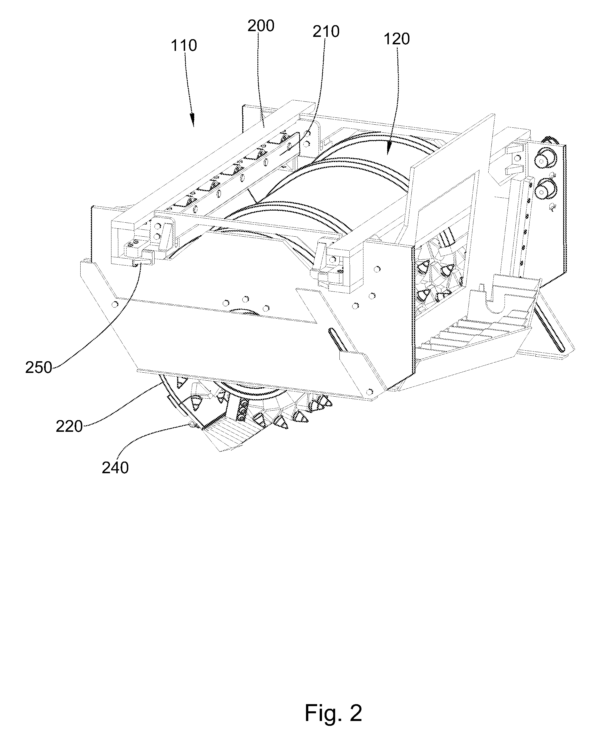
[0034]FIG. 2 discloses a milling chamber 110 comprising a rotary drum assembly 120 in mechanical communication with a guide 200. The guide 200 may interface with a track 210 supported by the underside of ...


PUM

PropertyMeasurementUnit
Lengthaaaaaaaaaa
Widthaaaaaaaaaa
Weightaaaaaaaaaa

Abstract

In one aspect of the invention, a system for exchanging a milling chamber comprises a vehicle comprising a milling chamber supported by the underside of the vehicle. The underside comprises a track that interfaces with a guide of the milling chamber. The track and guide are configured to accommodate lateral movement of the milling chamber with respect to a length of the vehicle.

Description

CROSS REFERENCE TO RELATED APPLICATIONS[0001]This application is a continuation of U.S. patent application Ser. No. 12 / 957,119, which is herein incorporated by reference for all that it contains.BACKGROUND OF THE INVENTION[0002]The present invention relates generally to road milling machines and especially to methods for replacing milling drums on road milling machines. Road milling machines typically comprise a vehicle body, self propelling mechanisms, and a rotary drum with a plurality of picks for degrading road surfaces. The rotary drum may be held within a drum housing that is secured to the underside of the vehicle body.[0003]During milling operations, picks may wear or break requiring maintenance of the drum before a job's completion. Such repairs delay projects and reduce profitability. The prior art has address mechanisms to quickly repair a damaged drum.[0004]U.S. Pat. No. 5,722,789 to Murray, which is herein incorporated by reference for all that it contains, discloses a ...

Claims


Application Information

Patent Timeline
IPC IPC(8): B02C23/00
CPCY10T29/49815Y10T29/49817E01C23/088Y10T29/53
Inventor HALL, DAVID R.JEPSON, JEFFMORRIS, THOMASWAHLQUIST, DAVIDBALLING, DANIEL
Owner KEJTERPILLAR R L
Why Eureka
Try Eureka