
Endoprosthesis for a joint, especially a finger, toe or wrist joint

a technology for a applied in the field of finger, toe or wrist joint, can solve the problems of limited passive rotation around the axis of the finger, pliant connection rod must fulfill a multiple number of tasks simultaneously, and bring its own disadvantages, and achieve the effect of little resistan

Inactive Publication Date: 2002-05-07
BAEHLER ANDRE +1
View PDF17 Cites 118 Cited by
  • Summary
  • Abstract
  • Description
  • Claims
  • Application Information

AI Technical Summary

Benefits of technology

It is thus the object of the invention to create an endoprosthesis for small joints, in which the mentioned disadvantages will be avoided, and a flexible connection of both joint parts that guarantees a play space will be assured. The connection will be loose enough and offers such little resistance, that the two parts can move freely, like the natural joint. The connection piece will not become fatigued. The movement play space of the joint will be definable with respect to rotation, extension, flexion and lateroflexion, and the latter will be dependent on extension, with a simultaneous loose holding together of the joint parts. An abrasion that is as small as possible will be assured.

Problems solved by technology

In addition, a limited passive rotation is possible around the axis of the finger.
Such a joint has the disadvantage that the pliant connection rod must fulfill a multiple number of tasks simultaneously.
However, this solution brings its own disadvantages.
If the threads are guided around the condyles, they rub against the condyles and do not assure sufficient safety from dislocation when the joint is bent.

Method used


Image

  • Endoprosthesis for a joint, especially a finger, toe or wrist joint
  • Endoprosthesis for a joint, especially a finger, toe or wrist joint
  • Endoprosthesis for a joint, especially a finger, toe or wrist joint

Examples


examples of embodiment

DESCRIPTION OF EXAMPLES OF EMBODIMENT

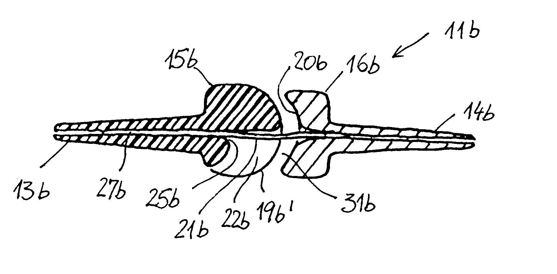
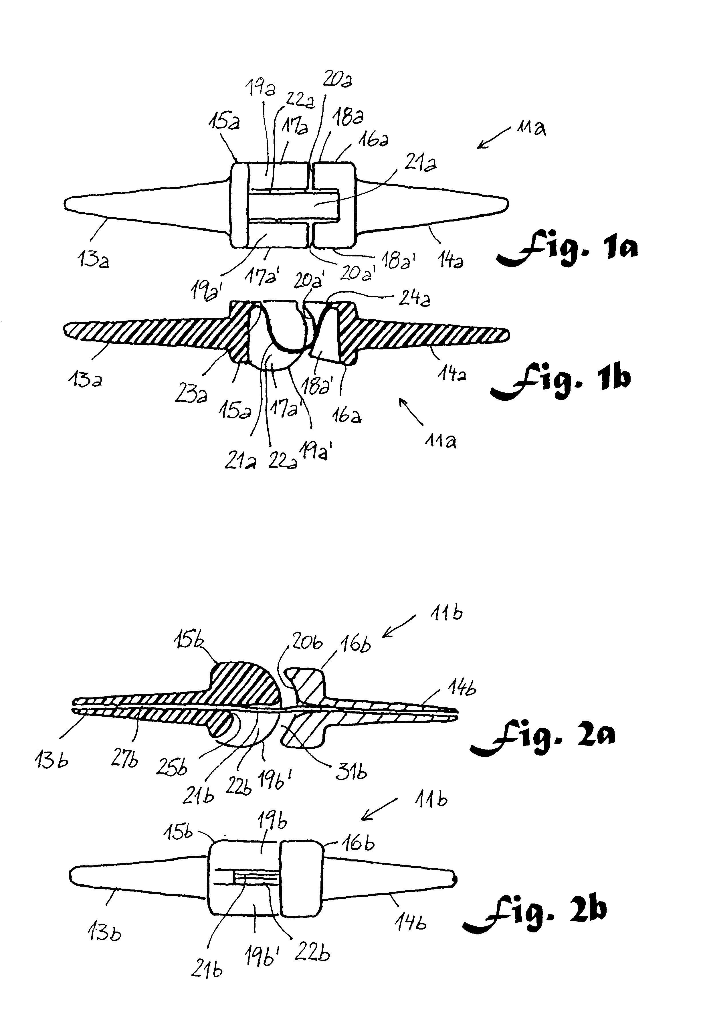
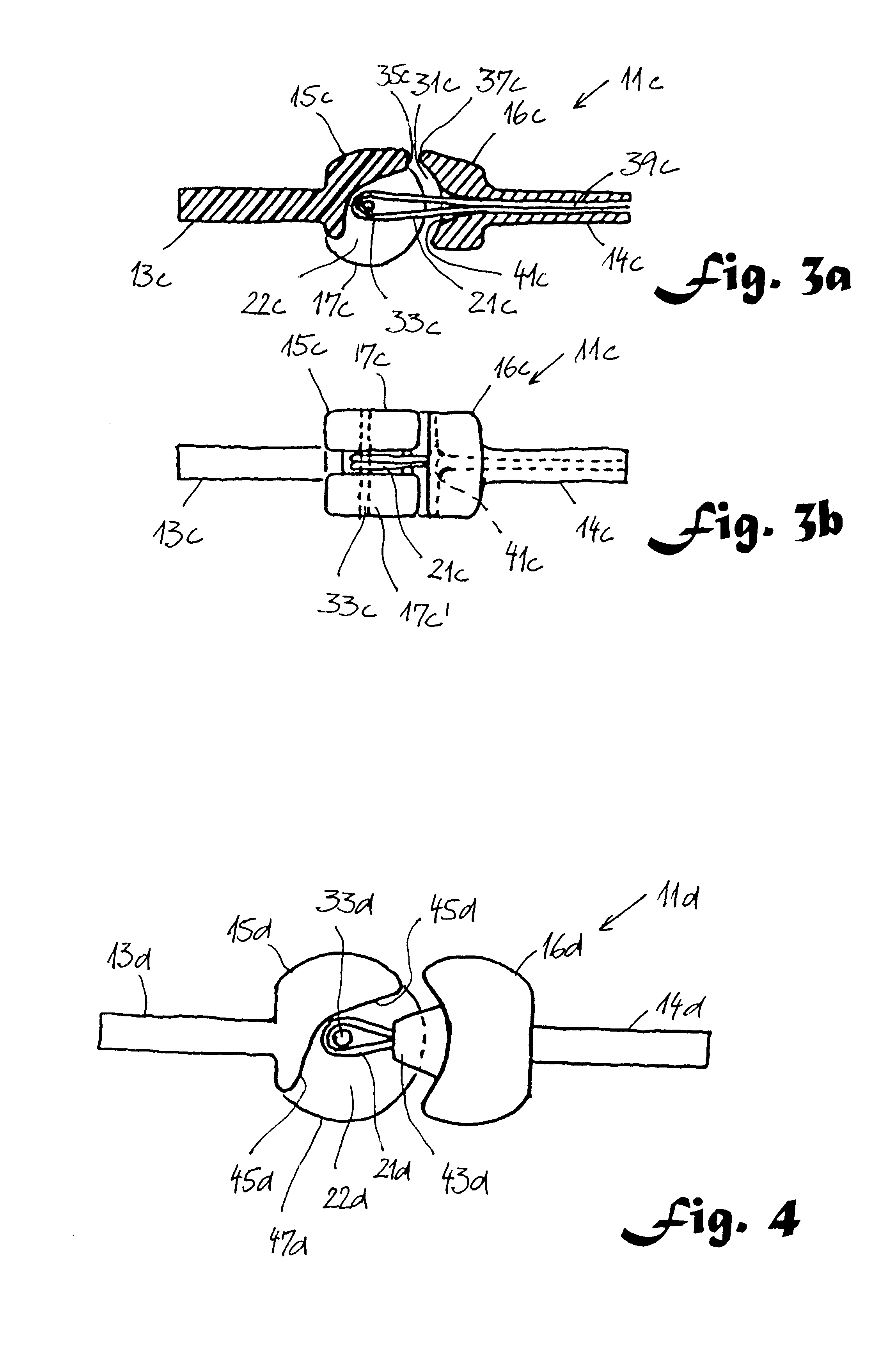
A very elementary example of embodiment of an endoprosthesis according to the invention is designated by 11a in FIG. 1. It is produced in one piece and has two pins 13a and 14a at two condyles 15a and 16a. Condyles 15a, 16a laterally have two head pieces 17a, 17a' and 18a, 18a', which form approximately equal and oppositely shaped sliding surfaces 19a, 19a' or 20a, 20a', respectively. A tape-type connection piece 21a is arranged in a central region between two such pairs of sliding surfaces. This connection piece 21a describes a curve arched between the two condyles 15a and 16a. It is separated laterally by head pieces 17a, 17a', 18a, 18a' and its beginning 23a and its end 24a are connected to a condyle 15a, 16a, each time. The transition from tape-type connection piece 21a to condyle 15a, 16a runs into the thickness. The tape-shaped connection piece 21a is now deformed upon flexion of the joint over its entire length. Thanks to its thin cross se...

embodiment

a, b . . . examples of embodiment

a, a' corresponding parts on either side of the connection piece for the same condyle

11 endoprosthesis

13 stem at the convex condyle for implanting in the bone marrow channel

14 stem at the concave condyle for implanting in the bone marrow channel

15 convex condyle

16 concave condyle

17 head part on one side

18 head part on the other side

19 sliding surfaces at the convex condyle

20 sliding surfaces at the concave condyle

21 connection piece, e.g. cord, tape . . .

22 depression, e.g. slot, groove

23 beginning of the connection piece

24 end of the connection piece

25 outlet place of the connection piece from the fastening channel

27 fastening channel

31 play space between the sliding surfaces

33 axis of rotation for the connection piece

35 stop

37 edge at the concave joint part

39 fastening opening

41 rounded outlet opening

43 elevation

45 edge of the depression 22, 49, forming an articulation stop for elevation 43, 50

47 edge of the side wall 55

49 depression, e.g. furrow, ...


PUM

PropertyMeasurementUnit
angleaaaaaaaaaa
flexibleaaaaaaaaaa
tensile forcesaaaaaaaaaa

Abstract

In an endoprosthesis (11h) for a joint, the two interacting joint parts (15h, 16h) are joined by a cord-type connection piece (21h), which is attached in the vicinity of the body axis (M2h, M2h') of the convex condyle (15h) and extends through a longitudinal groove (22h) in the flexion direction of the joint. The connection piece assures a play space (31h) between the contact surfaces (19h, h', 20h, h') of joint (11h). It is protected from friction on groove wall (55h, 55h') by an elevation (50h, 43h) in concave joint part (16h). An elevation (43h, 50h) at concave joint part (16h) and a depression (49h) at convex joint part (15h) interact in such a way that the lateral movement play space between depression and elevation determines the freedom of movement with respect to the lateroflexion of the joint. In preferred forms of embodiment, thanks to the spherical surfaces at least one pair of corresponding sliding surfaces (19h, 20h; 20h') on the two condyles lie flatly on one another, under load, in any position of the joint.

Description

The present invention concerns an endoprosthesis for a joint, particularly a finger, toe or hand joint, with a proximal and a distal joint part, of which one joint part in the flexion direction has an essentially convex contact surface around a body axis and the other has a correspondingly essentially concave contact surface, and which joint parts are joined by means of a flexible connection piece that takes up tensile forces, which piece has a thread-type or tape-type element.PRIOR ARTThe natural metacarpophalangeal joint (MCP) gives the finger a lateral freedom of movement, which differs each time depending on the flexion of the joint. In flexion, the degree of freedom is laterally zero to only a few degrees, but in extension it is approximately 30 degrees. In addition, a limited passive rotation is possible around the axis of the finger. The interphalangeal joint leaves free almost no movement play space laterally, independent of the flexion angle, and the joint parts can rotate ...

Claims


Application Information

Patent Timeline
Patent Type & Authority Patents(United States)
IPC IPC(8): A61F2/42A61F2/00A61F2/02A61F2/30
CPCA61F2/4241A61F2/4225A61F2230/0006A61F2/4261A61F2002/30062A61F2002/30113A61F2002/30332A61F2002/30362A61F2002/30369A61F2002/3037A61F2002/30448A61F2002/30451A61F2002/30462A61F2002/30464A61F2002/30563A61F2002/30594A61F2002/30632A61F2002/30639A61F2002/30642A61F2002/30662A61F2002/30738A61F2002/30878A61F2002/4251A61F2210/0004A61F2220/0033A61F2220/005A61F2220/0058A61F2220/0075
Inventor BAEHLER, ANDRESIMMEN, BEAT R.
Owner BAEHLER ANDRE
Learn More