Automotive Radar System and Method for Using Same

a technology for autonomic radar and vehicle, applied in the direction of using reradiation, measuring devices, instruments, etc., can solve the problems of relatively high system cost, inability of the driver of the vehicle to detect an object, and inability to always detect objects

Active Publication Date: 2012-05-31
NXP USA INC
View PDF4 Cites 73 Cited by
  • Summary
  • Abstract
  • Description
  • Claims
  • Application Information

AI Technical Summary

Problems solved by technology

As the vehicle approaches objects (e.g. other cars, pedestrians, and obstacles) or as objects approach the vehicle, a driver cannot always detect the object and perform intervention actions needed to avoid a collision with t...

Method used


Image

  • Automotive Radar System and Method for Using Same
  • Automotive Radar System and Method for Using Same
  • Automotive Radar System and Method for Using Same

Examples


Embodiment Construction

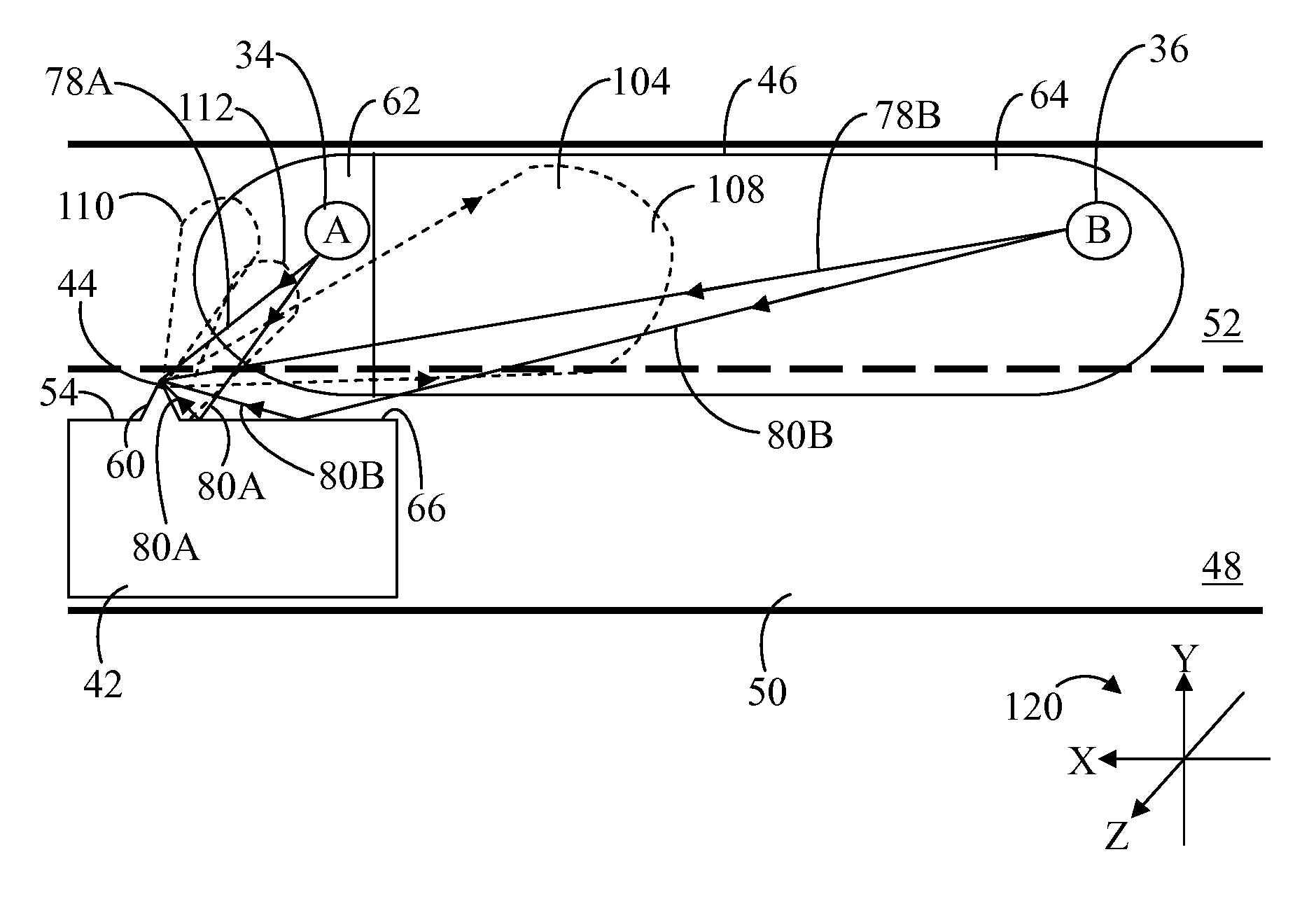
[0015]According to embodiments of the present disclosure, an automotive radar system and methodology are disclosed that apply a combination of multipath and directly propagated signal components, e.g., direct and indirect reflected radar signals, to detect objects in a side object detection system. Such a combination of direct and indirect reflected radar signals in a side object detection system allow the use of a simple single beam antenna to provide the sensitivity and angular coverage that would otherwise require a more complex and thus more costly multiple beam switched or scanning antenna system.

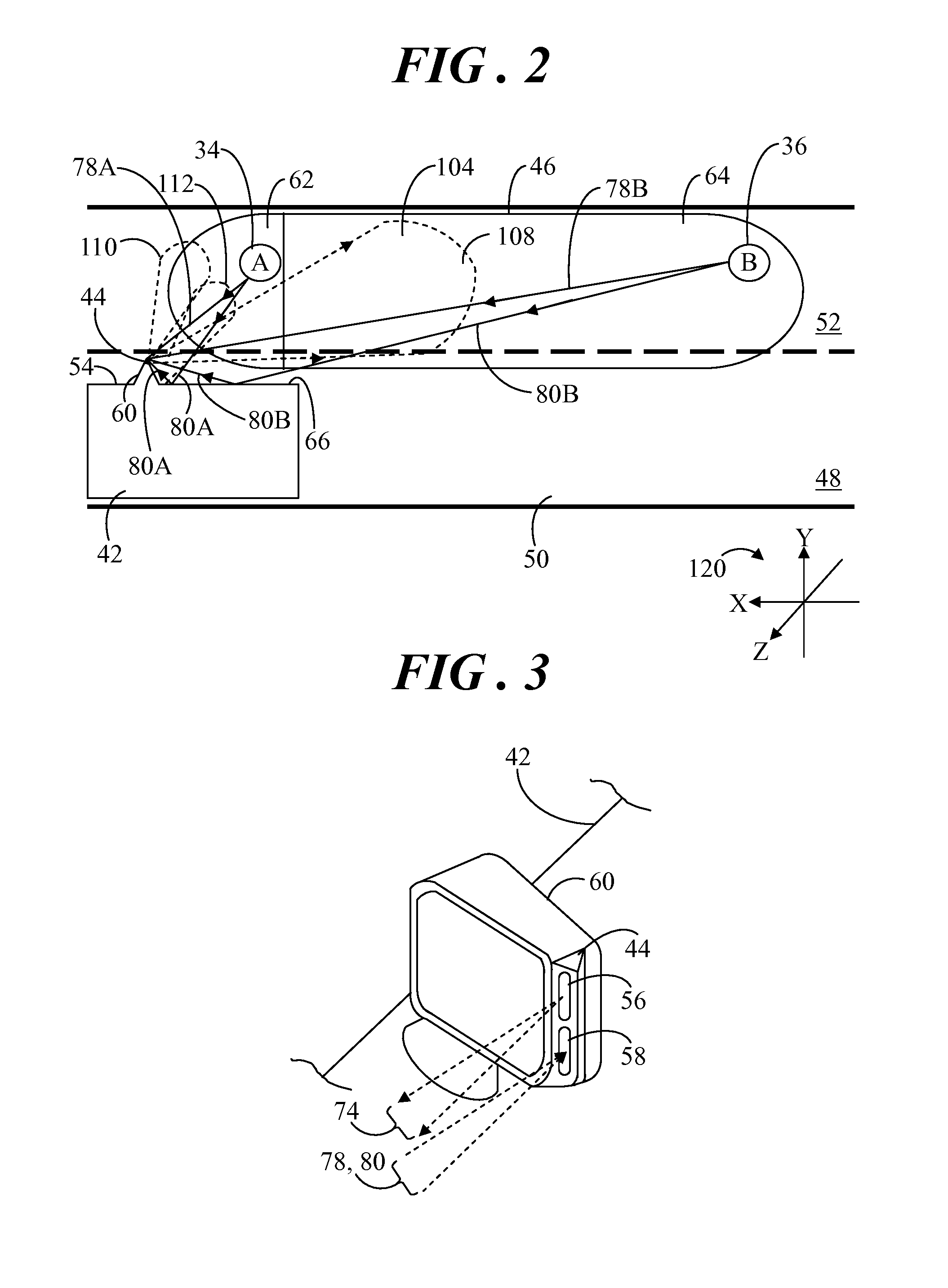
[0016]Referring to FIGS. 2-3, FIG. 2 shows a diagram of a vehicle 42 with an automotive radar system 44 disposed on a side thereof in accordance with an embodiment, and FIG. 3 shows a partial perspective view of automotive radar system 44 mounted on vehicle 42. Automotive radar system 44 may be utilized, for example, as a side object detection system for detecting objects in a target z...


PUM


Abstract

A radar system (44) for a vehicle (42) includes a transmit unit (56) and a receive unit (58). The transmit unit (56) includes a single beam antenna (72) for output of a radar signal (74) into a target zone (46). The receive unit (58) includes a single beam antenna (76) for receiving a direct receive signal (78) and an indirect receive signal (80). The receive signals (78, 80) are reflections of the radar signal (74) from an object (34, 36) in the target zone (46). The indirect receive signal (80) is reflected off the object (34, 36) toward a reflective panel (54) of the vehicle (42), and the indirect receive signal (80) is reflected off the reflective panel (54) for receipt at the receive antenna (76). The receive signals (78, 80) are summed to produce a detection signal (81) indicating presence of the object (34, 36) in the target zone (46).

Description

TECHNICAL FIELD OF THE INVENTION[0001]The present invention relates generally to radar systems for use in vehicles. More specifically, the present invention relates to a radar system for detecting objects in a target zone using multipath signal components of a single beam antenna.BACKGROUND OF THE INVENTION[0002]There is an increasing trend to include radar systems in commercially available automotive products such as automobiles, trucks, buses, and the like in order to provide a driver with enhanced awareness of objects around his or her vehicle. As the vehicle approaches objects (e.g. other cars, pedestrians, and obstacles) or as objects approach the vehicle, a driver cannot always detect the object and perform intervention actions needed to avoid a collision with the object. For example, a driver of a vehicle may not be able to detect an object in the so-called “blind spot” of the vehicle. This blind spot region varies depending on the type of vehicle, the size and seated positio...

Claims


Application Information

Patent Timeline
IPC IPC(8): G01S13/93G01S13/931
CPCG01S13/931G01S2013/462G01S2013/9389G01S2013/9382G01S2013/9385G01S2013/9332G01S2013/93273G01S2013/9315G01S2013/93275G01S2013/93274
Inventor MACDONALD, JAMES D.RUBIN, LAWRENCE A.
Owner NXP USA INC
Why Eureka
Try Eureka