Method for Determining the Geographic Coordinates of Pixels in SAR Images

a technology of geographic coordinates and sar images, applied in the direction of using reradiation, radio wave reradiation/reflection, measurement devices, etc., can solve the problems of azimuth errors, distortion effects, and inability to accurately determine the position of targets at great distances (20 km-100 km), so as to reduce the error in position determination

Active Publication Date: 2012-05-31
AIRBUS DEFENCE & SPACE
View PDF4 Cites 18 Cited by
  • Summary
  • Abstract
  • Description
  • Claims
  • Application Information

AI Technical Summary

Benefits of technology

[0017]In the determination of coordinates for a target from an SAR image using the approach familiar from prior art, the above-described cone contributes to determining the coordinates of the target. However, the position of this cone in space is determined relative to the velocity vector. If this velocity vector is not known precisely, then an error results in the coordinate determination. In typical SAR systems, this error can amount to up to 100 meters in the azimuth direction, the direction of the velocity vector. In addition, the assumption is made based on the determination of the geographic coordinates of the image center that the target plane is flat. However, SAR produces typical effects such as foreshortening or layover, a displacement of the pixel corresponding to the target point, and this results in an additional error in the calculation of the displacement vector to the target.
[0018]Exemplary embodiments of the present invention provide a method by which the error in the position determination can be reduced.

Problems solved by technology

Using SAR image to determine the position of a target at great distances (20 km-100 km) is frequently imprecise due to the errors in the SAR images.
The errors in the SAR images typically result from azimuth errors and distortion effects.
The optimum viewing direction for an SAR is 90° relative to the direction of velocity vector v. Viewing directions that deviate from the optimum viewing direction negatively affect the resolution and the cost / complexity of SAR image generation.
If this velocity vector is not known precisely, then an error results in the coordinate determination.
In typical SAR systems, this error can amount to up to 100 meters in the azimuth direction, the direction of the velocity vector.
However, SAR produces typical effects such as foreshortening or layover, a displacement of the pixel corresponding to the target point, and this results in an additional error in the calculation of the displacement vector to the target.

Method used


Image

  • Method for Determining the Geographic Coordinates of Pixels in SAR Images
  • Method for Determining the Geographic Coordinates of Pixels in SAR Images
  • Method for Determining the Geographic Coordinates of Pixels in SAR Images

Examples


Embodiment Construction

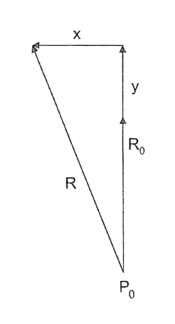
[0026]Obtaining distance information from an SAR image proceeds as follows. In an SAR system, the range gate is set for the generation of images. This range gate determines the distance between the SAR sensor and the resolution cell on the ground that corresponds to the center of the SAR slant range image. Hereafter this pixel is identified as the center pixel. Once a pixel has been determined as the target, the distance to the resolution cell on the ground corresponding to the pixel can be calculated. This is illustrated in FIG. 3.

[0027]The range gate is denoted in FIG. 3 as R0. The distance to the target pixel is denoted by R. If the pixel coordinates x and y of the target pixel are provided relative to the center pixel, the distance R to this pixel can be computed, as follows

R=√{square root over ((δxx)2+(δyy+R0)2)}{square root over ((δxx)2+(δyy+R0)2)}  (1)

[0028]The parameters δx and δy denote the resolution of the SAR slant range image in the azimuth direction or the resolution i...


PUM


Abstract

A method for effecting the airborne determination of geographic coordinates of corresponding pixels from digital synthetic aperture radar images, where the SAR images are available in the form of slant range images and the recording position of the respective SAR image is known. The coordinates of the corresponding pixels in the SAR images and the corresponding range gates are used in each case to determine the distance between a corresponding resolution cell on the ground and the respective recording position of the respective SAR image. The determined distances and associated recording positions of the SAR images are used to determine the geographic coordinates of the corresponding pixels in the SAR images by employing a WGS84 ellipsoid.

Description

CROSS-REFERENCE TO RELATED APPLICATIONS[0001]The present application claims priority under 35 U.S.C. §119 to German Patent Application No. 10 2009 030 672.2, filed Jun. 25, 2009, the entire disclosure of which is herein expressly incorporated by reference.BACKGROUND AND SUMMARY OF THE INVENTION[0002]Exemplary embodiments of the present invention are directed to a method for determining the geographic coordinates of pixels in SAR images.[0003]Using SAR image to determine the position of a target at great distances (20 km-100 km) is frequently imprecise due to the errors in the SAR images. The errors in the SAR images typically result from azimuth errors and distortion effects. (foreshortening, layover).[0004]U.S. Pat. No. 5,659,318 A discloses an interferometric method in which images of a target region generated using two spatially separated SAR antennas are analyzed in terms of their phase difference, and the recording position of the SAR images is known.[0005]The known approach t...

Claims


Application Information

Patent Timeline
Patent Type & Authority Applications(United States)
IPC IPC(8): G01S13/90
CPCG01S7/295G09B29/10G01S13/90
Inventor BENNINGHOFEN, BENJAMINKOBAN, TAMERSTAHL, CHRISTOPH
Owner AIRBUS DEFENCE & SPACE
Why Eureka
Try Eureka