
Water barrier device

a technology of watertight doors and barriers, which is applied in the direction of buttress dams, marine site engineering, construction, etc., can solve the problems of blocking traffic by the banks, affecting the safety of the public, and the normal living environment deteriorating, so as to prevent damage

Inactive Publication Date: 2012-05-31
FUJITA HIDEKI +2
View PDF5 Cites 8 Cited by
  • Summary
  • Abstract
  • Description
  • Claims
  • Application Information

AI Technical Summary

Benefits of technology

[0007]An object of the present invention is to provide a water barrier device capable of being prevented from being damaged by impacts from vehicles and the like.
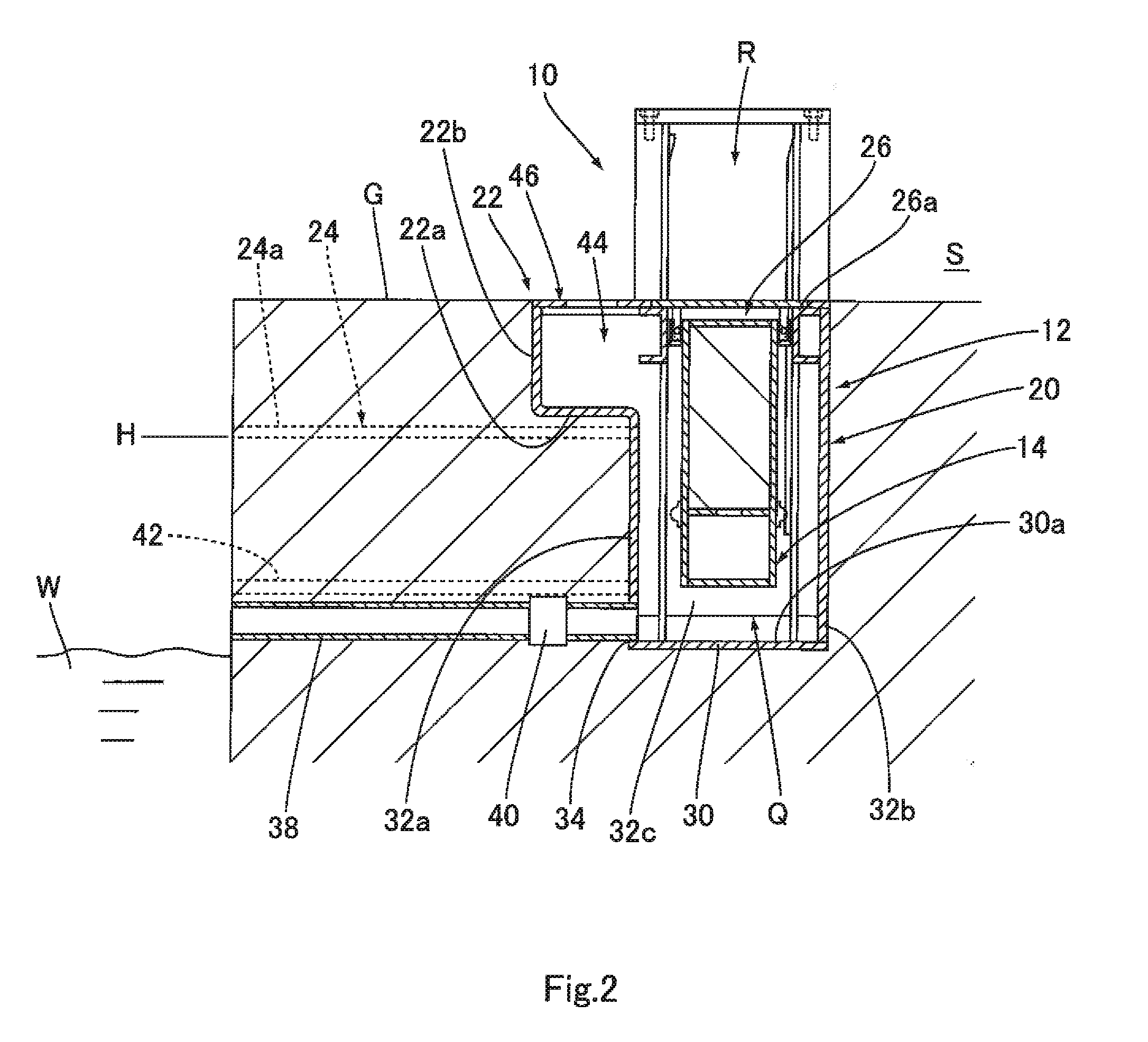
[0009]According to this configuration, in the first state where the water is not stored in the water storage tank, the lid portion contacts the inner peripheral portion of the opening. Thus, the passage is opened, and the opening is closed. In addition, the space is secured between the lower end portion of the water barrier wall and the bottom surface of the water storage tank, and the movements of the lower end portion of the water harrier are allowed in this space. Therefore, even in a case where impacts are applied to the lid portion from people or vehicles going through the passage, the impacts can be absorbed by the movements of the lower end portion of the water barrier wall. Thus, the water barrier wall and the float portion can be prevented from being damaged by the impacts. In contrast, in the second state where the water is stored in the water storage tank, the lid portion and the water barrier wall move up together with the float portion. Thus, the water barrier wall projects toward the passage through the opening, and the passage is closed. Therefore, the flow of the water flowing through the passage can be blocked quickly and surely without relying on humans or electric power. Moreover, according to this configuration, the space is formed by the lower end portion of the water barrier wall, the bottom surface of the water storage tank, and the side wall of the water storage tank, and the first discharge port to which the first discharge pipe is connected is formed at the portion of the side wall of the water storage tank, the portion constituting the space. Therefore, while applying the pressure to the water in the space by the weight of the water barrier portion, the water can be discharged through the first discharge pipe in a short period of time. Further, according to this configuration, the water stored in the water storage tank can be guided to the first discharge port and the first discharge pipe by the inclined bottom surface of the water storage tank.
[0011]According to this configuration, since the float portion is arranged between two wall plates constituting the water barrier wall, the vertical length of a portion where the water barrier wall and the float portion overlap can be shortened. Thus, the entire device can be reduced in size. In addition, the strength of the water barrier wall earl be increased by these two wall plates.

Problems solved by technology

However, if the banks are constructed, traffic is blocked by the banks.
Therefore, normal living environment may deteriorate.
However, the problems are that: in the case of moving the watertight door by humans, the opening and closing of the watertight door cannot be performed quickly; and in the case of moving the watertight door by electric power (a motor or the like), the watertight door does not move in the event of power outage.
However, since the float and the tide prevention plate are sandwiched between a metal cover plate and a bottom surface of the underground pit made of ferroconcrete at normal times, there is no place to which the impacts transferring from the vehicles and the like to the cover plate can escape, and there is a possibility that the impacts may damage the float and the tide prevention plate.

Method used


Image

  • Water barrier device
  • Water barrier device
  • Water barrier device

Examples


embodiment 1

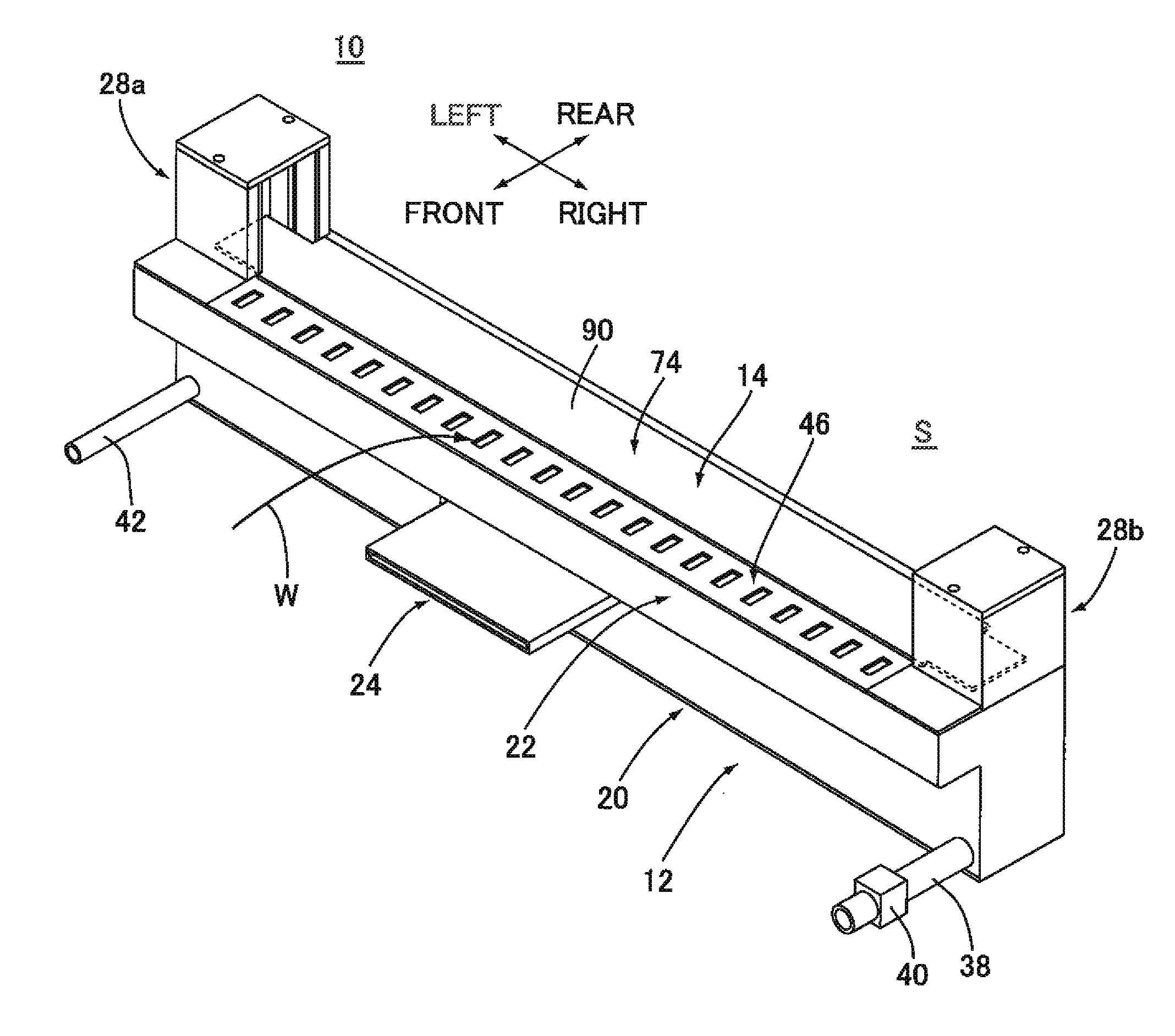
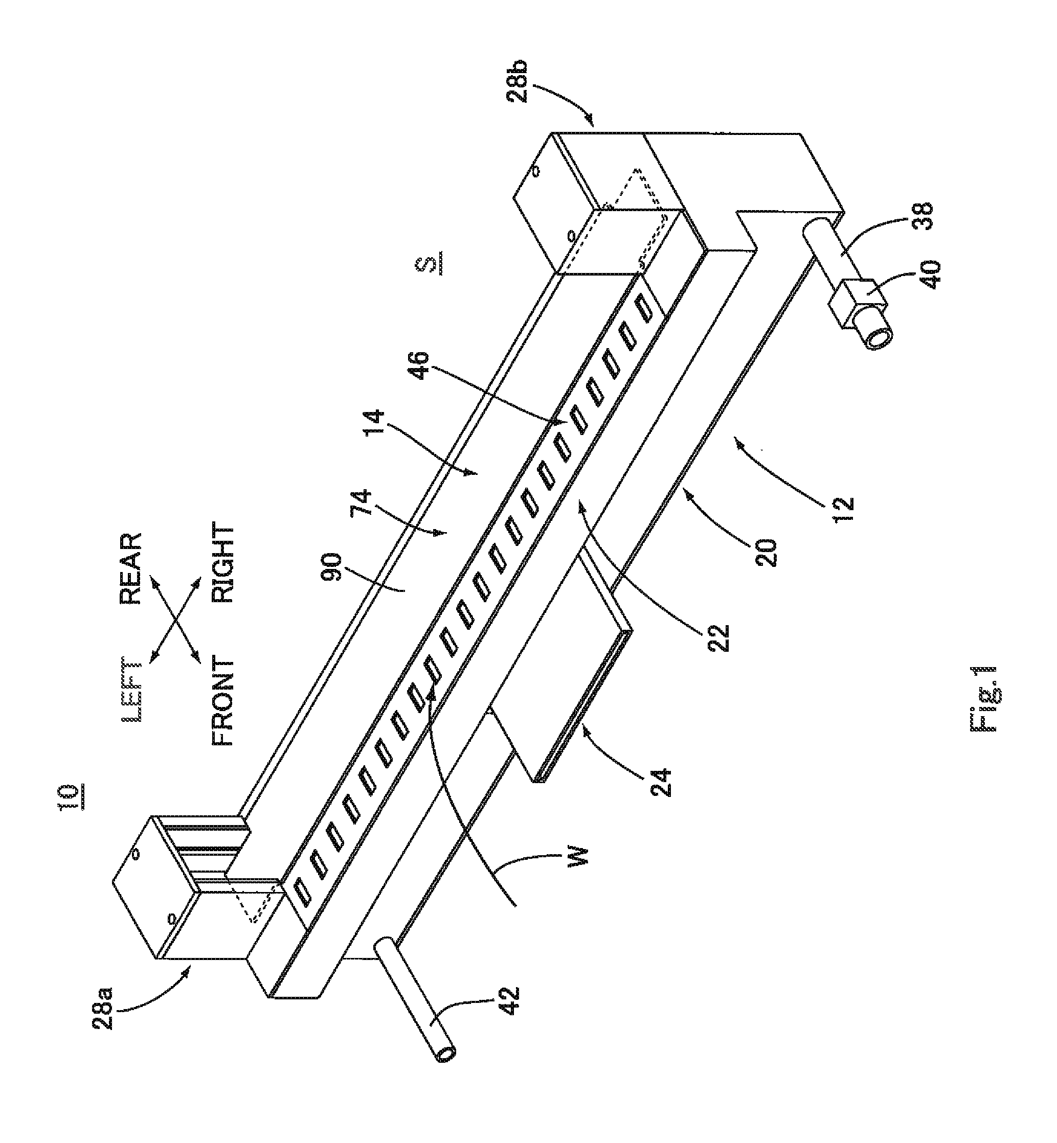
[0029]FIG. 1 is a perspective view showing the configuration of a water barrier device 10 according to FIG. 2 is a cross-sectional view showing a usage state (first state) of the water barrier device 10. FIG. 3 is an exploded perspective view showing the configuration of the water barrier device 10. FIG. 4 is a front view showing the configuration of the water barrier device 10.

[0030]As shown in FIG. 2, the water barrier device 10 is configured to block the flow of water W toward a flooding prevention area S, such as a residential area, at the time of tsunamis or floods and includes a water storage portion 12 provided under a passage R and a water barrier portion 14 accommodated in the water storage portion 12. The passage R is provided at a place through which the water W flows toward the flooding prevention area S at the time of tsunamis or floods. At normal times, people and vehicles M (FIG. 7) can go through the passage R. As shown by arrows in FIG. 1, in the present embodiment...

embodiment 2

[0056]FIG. 9 is a partial cross-sectional view showing the configuration of a water barrier device 100 according to In the water barrier device 100, a lid main body 106 of a lid body 104 constituting a water barrier portion 102 is formed to be bent in a circular-arc shape. The lid main body 106 in an arch shape extends between the front lid receiving portion 50 and the rear lid receiving portion 52. Therefore, the withstand load of the lid main body 106 can be improved while suppressing the increase in thickness of the lid main body 106. In FIG. 9, the same reference signs are used for the components corresponding to the components of the water barrier device 10 (the same is true for FIGS. 10 and 11).

embodiment 3

[0057]FIG. 10 is a partial cross-sectional view showing the configuration of a water barrier device 110 according to In a water barrier portion 112 of the water barrier device 110, a lid main body 114a constituting a lid body 114 and a top plate 116a constituting a water barrier wall 116 are formed as one component, and the lid body 114 and water barrier wall 116 are integrally formed. Therefore, the number of parts of the water barrier portion 112 can be reduced, and the weight of the barrier portion 112 can be reduced. In addition, the manufacturing cost can also be reduced.

[0058]FIG. 11 is a front view showing the configuration of a water barrier device 120 according to Embodiment 4. In the water barrier device 120, a bottom surface 122a of a water storage tank 122 is inclined so as to become lower from both left-right-direction end portions thereof toward a left-right-direction center portion thereof, and the first discharge port 34 is provided at a lower portion of a left-righ...


PUM


Abstract

A water bather device includes: a water storage portion provided under a passage and a water barrier portion. In a first state, the water barrier wall is suspended and supported by the lid portion such that a space is formed by a lower end portion of the water barrier wall, a bottom surface of the water storage tank, and a side wall of the water storage tank. In a second state, the water barrier wall projects with respect to the passage through the opening. A first discharge port is connected is formed at a portion of the side wall of the water storage tank, the portion constituting the space, and a bottom surface of the water storage tank is inclined so as to become lower toward the first discharge port in a transverse direction of the passage.

Description

BACKGROUND OF THE INVENTION[0001]1. Field of the Invention[0002]The present invention relates to a water barrier device configured to block the flow of water toward residential areas and the like at the time of tsunamis and floods.[0003]2. Description of Related Art[0004]To prevent the residential areas and the like from being flooded by tsunamis or floods, it is effective to construct banks at the seaside or riverside. However, if the banks are constructed, traffic is blocked by the banks. Therefore, normal living environment may deteriorate. Conventionally, a part of the banks is cut out, a passage is provided thereat, and a sliding type watertight door is provided on the passage. At normal times, the watertight door is open, and vehicles and people can go therethrough. If there is a possibility that tsunamis, floods, or the like may occur, the watertight door is closed, and the ingress of water into the residential areas and the like is prevented. However, the problems are that: ...

Claims


Application Information

Patent Timeline
Patent Type & Authority Applications(United States)
IPC IPC(8): E02B7/22E02B7/28
CPCE02B7/205E02B3/104
Inventor FUJITA, HIDEKI
Owner FUJITA HIDEKI
Learn More