
Method for producing a large-caliber explosive projectile, and an explosive projectile produced using this method

a technology of explosive projectiles and projectiles, which is applied in the direction of ammunition loading, other domestic articles, weapons, etc., can solve the problems of excessive time-consuming of liner, and achieve the effect of avoiding creasing and avoiding further processing steps

Inactive Publication Date: 2012-06-07
RHEINMETALL WAFFE MUNITION GMBH
View PDF7 Cites 0 Cited by
  • Summary
  • Abstract
  • Description
  • Claims
  • Application Information

AI Technical Summary

Benefits of technology

The present invention provides a method for producing a large-caliber explosive projectile with a plastic-bonded explosive charge. The method involves producing a two-part projectile casing with an ogival front part and an annular front projectile casing section that contains the mouth hole. The two parts are then connected together with a screw connection. The invention also provides a modified method where the front projectile casing section is adhesively bonded or sealed to the inner wall of the projectile casing. The invention also provides a modified method where the front projectile casing section is connected to the tail-end projectile casing section with a screw connection and the front end of the front projectile casing section is closed with an elastic compensation element. The invention also provides a modified method where the front projectile casing section is closed with a cover and the elastic compensation element is composed of an open-pore foam. These modifications improve the stability and reliability of the projectile.

Problems solved by technology

The primary disadvantage of this known method is that the mouth hole, which is designed for a nose fuze to be screwed into, has a small diameter, as a result of which both the introduction into and the positioning of the liner in the internal area of the projectile casing, and the introduction of the explosive charge, which can be cast and is generally highly viscous, into the liner are extraordinarily time-consuming.

Method used


Image

  • Method for producing a large-caliber explosive projectile, and an explosive projectile produced using this method
  • Method for producing a large-caliber explosive projectile, and an explosive projectile produced using this method

Examples


Embodiment Construction

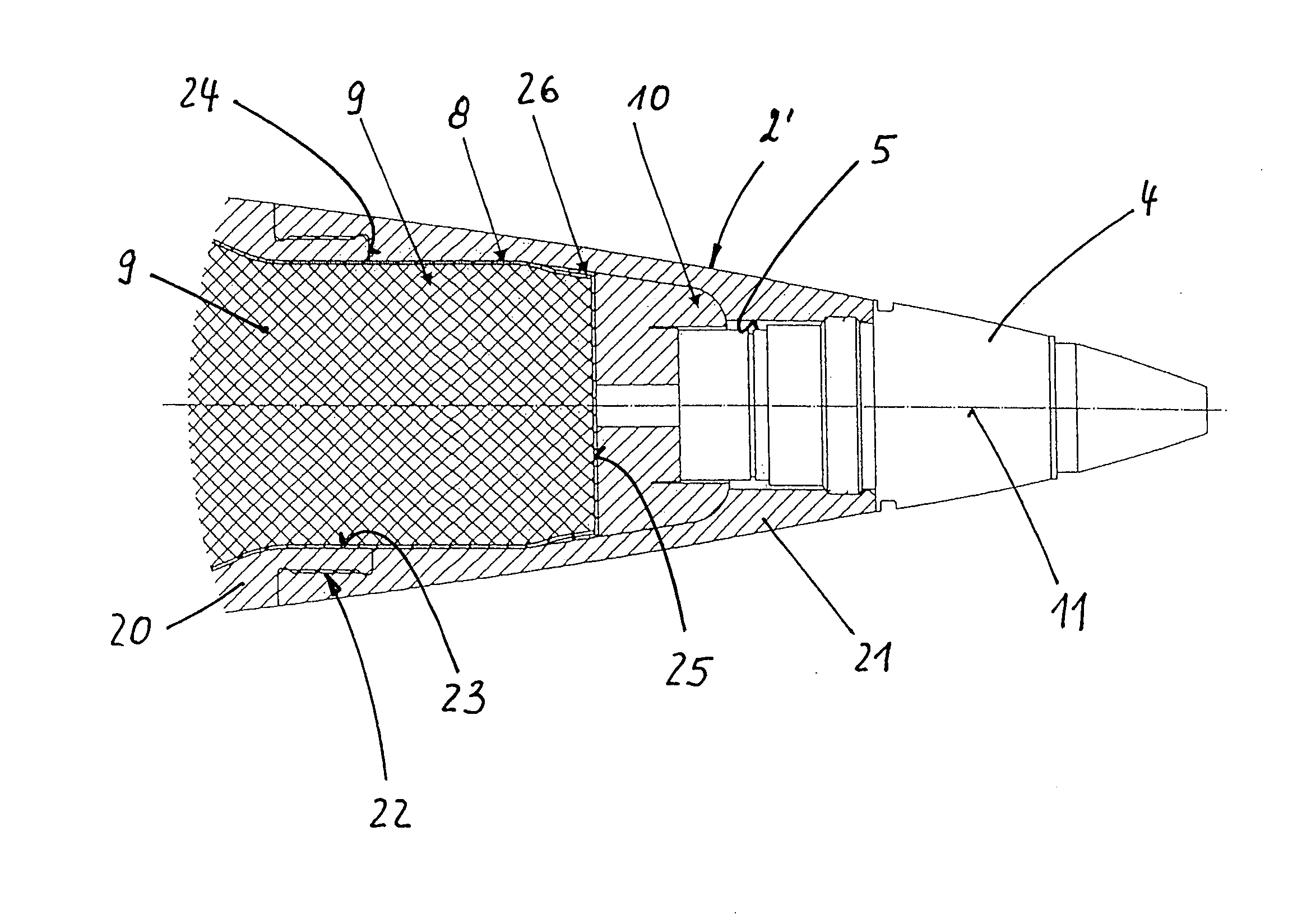
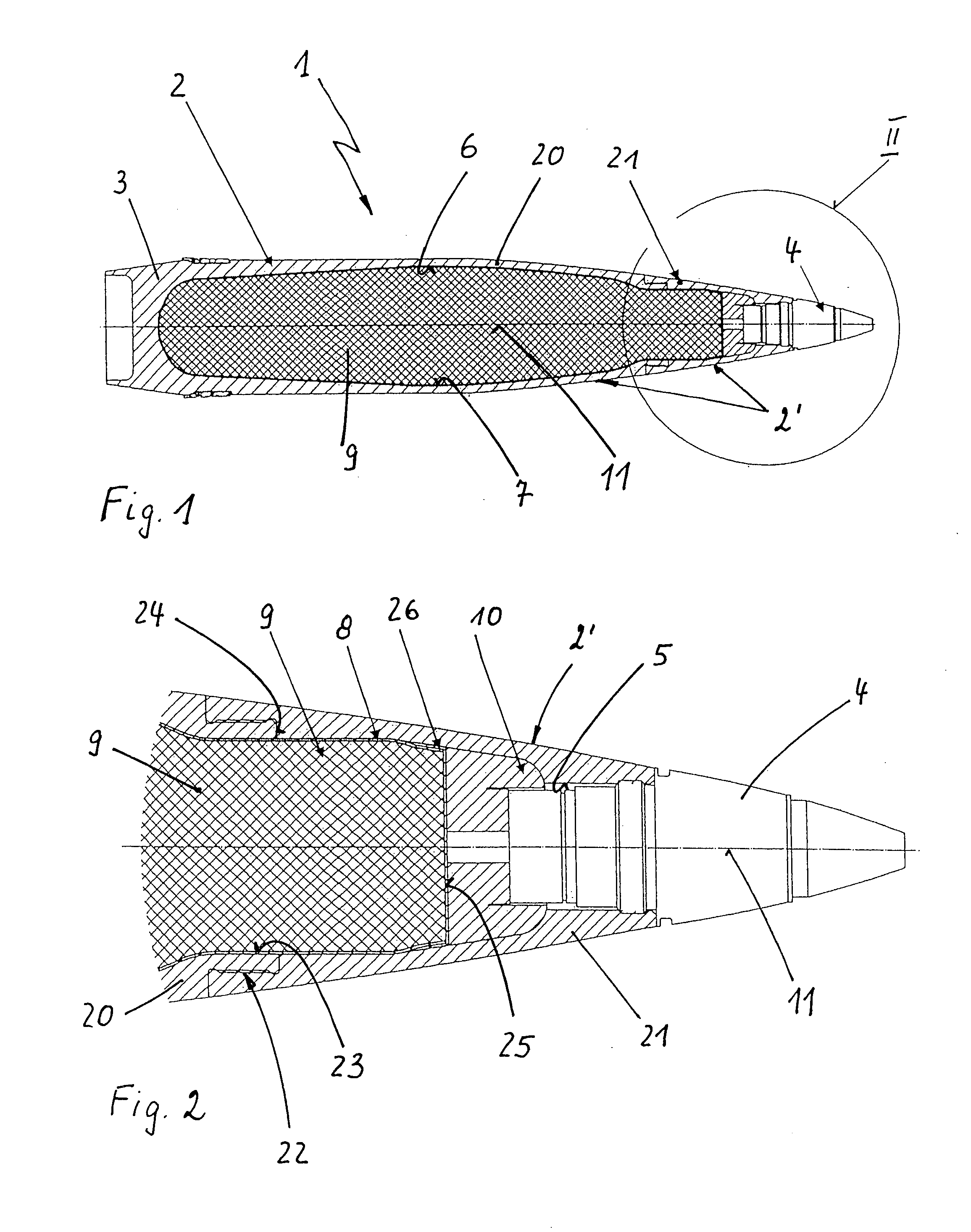
[0016]In FIG. 1, 1 denotes a large-caliber, spin-stabilized explosive projectile, as can be fired from an armored-vehicle howitzer, for example. The explosive projectile 1 comprises a projectile casing 2 with an ogival front part 2′, a bottom part 3 and a front-end nose fuze 4. The nose fuze 4 is screwed into a mouth hole 5, which is arranged at the tip end in the projectile casing 2.

[0017]The projectile casing 2 surrounds an internal area 6, to whose internal walls 7 an elastic casing (liner) 8, which is composed of plastic, is adhesively bonded.

[0018](10) A plastic-bonded, insensitive explosive charge 9 is located in the liner 8. In other words, the explosive charge 9 is contained within the liner 8 as shown in FIG. 1.

[0019]At the front end, the explosive charge 9 is closed by an elastic compensation element 10, on whose side facing away from the explosive charge 9 the front area of the internal wall of the projectile casing 2 and the nose fuze 4 exert a predeterminable pressure, ...


PUM


Abstract

A method is provided for producing a large-calibre explosive projectile having a projectile casing with an ogival front part, which surrounds an internal area filled with a plastic-bonded explosive charge and, at a nose end, has a mouth closed by a nose fuze, wherein an elastic liner is arranged between the explosive charge and the inner wall of the projectile casing. The projectile casing is produced in two parts, such that, in the direction of the longitudinal axis of the projectile casing, a tail-end projectile casing section and an annular front projectile casing section, which contains the mouth, can be connected to one another in the area of the ogival front part, via a screw connection. The liner is introduced into the tail-end projectile casing section and the explosive charge is introduced into the liner before the two projectile casing sections are connected to one another.

Description

[0001]This is a National Phase Application in the United States of International Patent Application No. PCT / EP2010 / 002795 filed May 6, 2010, which claims priority on German Patent Application No. 10 2009 022 495.5, filed May 25, 2009. The entire disclosures of the above patent applications are hereby incorporated by reference.FIELD OF THE INVENTION[0002]The invention relates to a method for producing a large-caliber explosive projectile having a projectile casing with an ogival front part, which projectile casing surrounds an internal area that is filled with a plastic-bonded explosive charge, and which projectile casing has a mouth hole, which can be closed by a nose fuze, at the tip end. The invention also relates to a large-caliber explosive projectile produced using this method.BACKGROUND OF THE INVENTION[0003]By way of example, a method in accordance with the field of the invention is known from document EP 1 338 860 B1. In this case, a casing, which is composed, for example, o...

Claims


Application Information

Patent Timeline
Patent Type & Authority Applications(United States)
IPC IPC(8): F42B12/20F42B33/02
CPCF42B12/207F42B30/08F42B33/001F42B33/0214F42B33/0207
Inventor DAU, OLENADERHOFF, UWE
Owner RHEINMETALL WAFFE MUNITION GMBH
Learn More