Display device

Active Publication Date: 2012-06-07
YAZAKI CORP
View PDF5 Cites 6 Cited by
  • Summary
  • Abstract
  • Description
  • Claims
  • Application Information

AI Technical Summary

Benefits of technology

[0013]According to the first aspect of the invention as described above, the light from the first light emitting elements passes through the diffusion plate. Therefore, the diffusion plate emits light in the areas corresponding to the number of the first emitting elements, that is, a display level. Then, since a predetermined number of first light emitting elements from the other end in the arrangement direction among the emitting first light emitting elements are made to emit light with decreasing brightness towards the other end, the portion of the diffusion plate emits light wi

Problems solved by technology

The liquid crystal indicator is capable of displaying the bar graph with good appearance, but the cost is high.
However, the above described LED display device has a problem of lacking design properties as compared with a liquid crystal indicator.
In addition, when the d

Method used


Image

  • Display device
  • Display device
  • Display device

Examples


Example

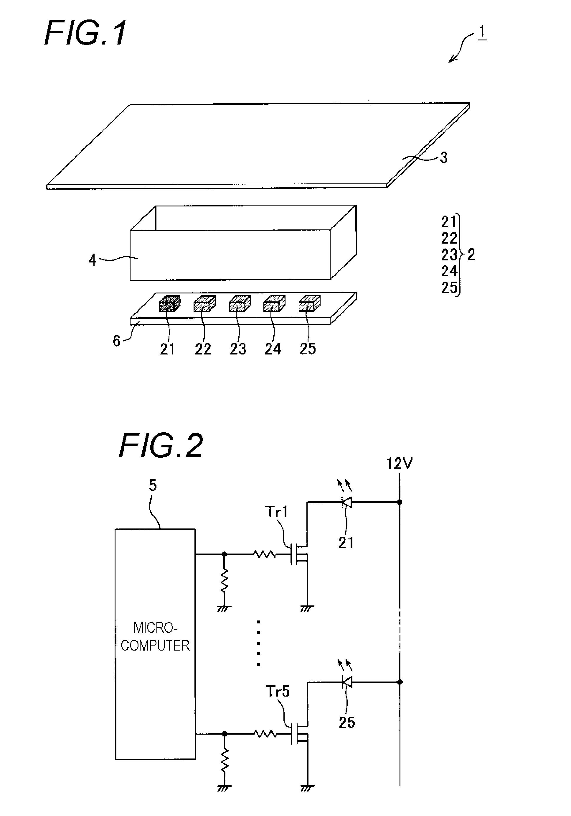
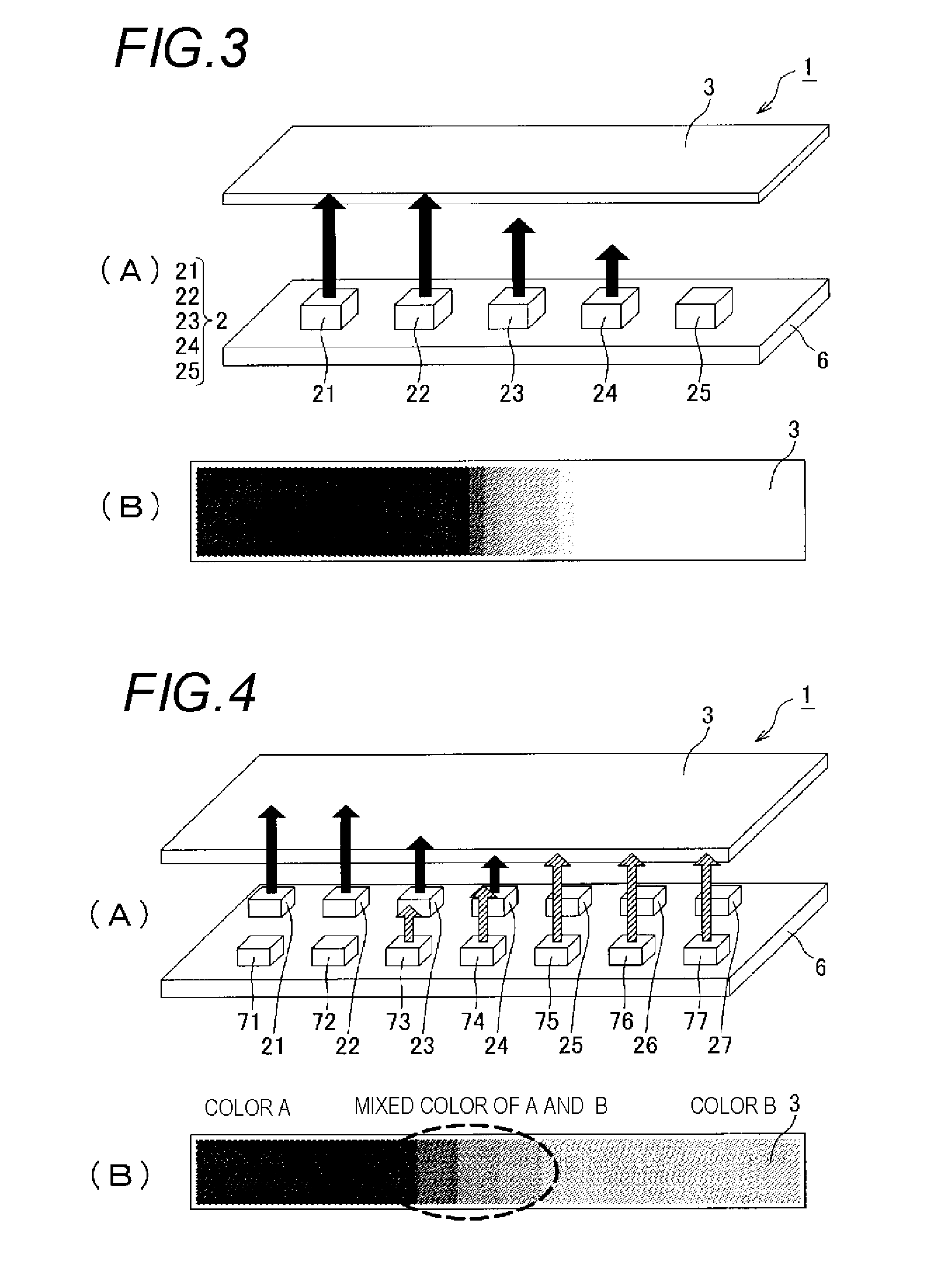
[0027]A first embodiment of the invention is explained below with reference to FIGS. 1 to 3. As shown in FIGS. 1 and 2, a display device 1 includes a first LED group 2 which is a group of first light emitting elements, a diffusion plate 3 (FIG. 1), a casing 4 (FIG. 1) and a microcomputer 5 (FIG. 2). The first LED group 2 includes first LEDs 21 to 25, which are a plurality of first light emitting elements arranged on a substrate 6 in a line. As shown in FIG. 2, each of the first LEDs 21 to 25 has two terminals. One terminal is connected to a 12V power supply, and the other is connected to a ground via one of transistors Tr1 to Tr5. When the transistors Tr1 to Tr5 are turned on, the first LEDs 21 to 25 are supplied with the 12V power supply. Then, the first LEDs 21 to 25 emit light of the same color (color A) as each other.

[0028]As shown in FIG. 1, the diffusion plate 3 is arranged at a front side of the first LED group 2 and is formed to be an elongated shape along the arrangement di...

Example

Second Embodiment

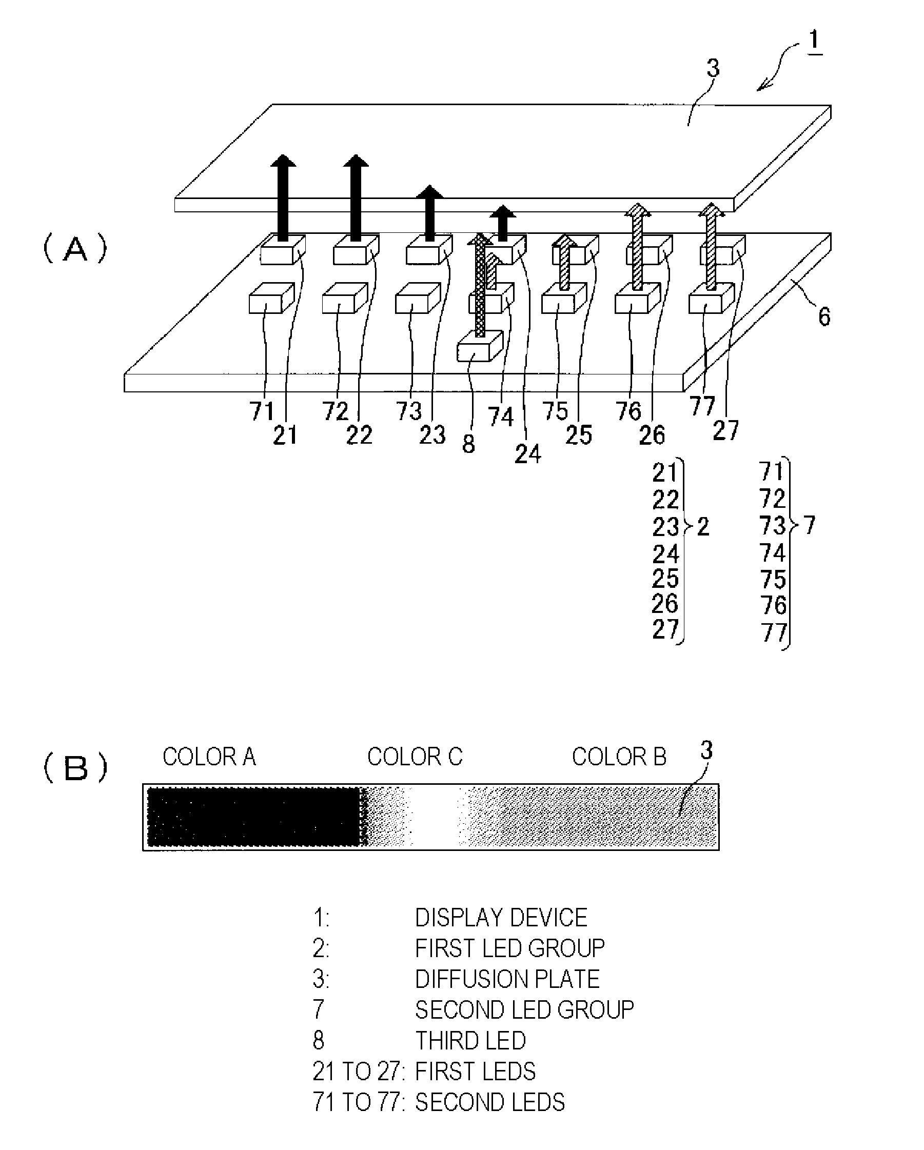
[0033]Next, a second embodiment of the invention is explained with reference to FIG. 4. In the figure, parts that are the same as those of the display device 1 explained in the above described first embodiment of FIGS. 1 to 3 are given the same symbols, and their detailed description is omitted. A major difference between the first embodiment and the second embodiment is that besides the first LED group 2 that includes the first LEDs 21 to 27, the display device 1 further includes a second LED group 7 (a group of second light emitting elements). In the first embodiment, the first LED group 2 includes five first LEDs 21 to 25, while in the second embodiment, the first LED group 2 includes seven first LEDs 21 to 27. In addition, the second LED group 7 includes a plurality of second LEDs 71 to 77 arranged on the substrate 6 in a line and in parallel with the first LED group 2.

[0034]Similar to the first LEDs 21 to 27, each of the second LEDs 71 to 77 has two terminals....

Example

Third Embodiment

[0039]Next, a third embodiment of the invention will be explained with reference to FIG. 5. In the figure, parts that are the same as those of the display device explained in the above described second embodiment in FIG. 4 are given the same symbols, and their detailed description will be omitted. A major difference between the second embodiment and the third embodiment is that the display device 1 includes a third LED 8. The third LED 8 is disposed at a position corresponding to a specified detection value (specified display level) and next to the first LED group 2 and the second LED group 7. In this embodiment, the third LED 8 is disposed in the center of the arrangement directions of the first LEDs 21 to 27 and the second LEDs 71 to 77.

[0040]Similar to the first LEDs 21 to 27 and the second LEDs 71 to 77, the third LED 8 has two terminals. One terminal is connected to the 12V power supply, and the other is connected to a ground via a transistor (not shown in the ...


PUM


Abstract

Provided is a display device in which design properties have been improved by eliminating the flickering when the display level changes. A microcomputer (5) causes light emission of first LEDs (23 and 24) which are the first and second ones counting from the right end among the emitting first LEDs (21 to 24), with decreasing brightness towards the right end. Furthermore, the microcomputer (5) causes light emission of second LEDs from a second LED (77) which is disposed at the right end of the second LEDs (71 to 77), to a second LED (73) which is disposed at a position overlapped with the first LEDs (23 and 24) that emit light with decreasing brightness towards the right end, and also causes light emission of second LEDs (73 and 74), which are the first and second ones counting from the left end among the emitting second LEDs (73 to 77), with decreasing brightness towards the left end.

Description

TECHNICAL FIELD [0001]The present invention relates to a display device, and more particularly, to a display device including a group of first light emitting elements which includes a plurality of first light emitting elements arranged in a line, and a light emission controlling unit, which displays a display level by making light emitting elements to emit light that ranges from one end of the first light emitting elements in the arrangement direction of the group of first light emitting elements to the first light emitting element at a position corresponding to a display level to be indicated.BACKGROUND ART [0002]As a display device for displaying the above described display level, it is known that, for example, a liquid crystal indicator is used to display a bar graph. The liquid crystal indicator is capable of displaying the bar graph with good appearance, but the cost is high. Therefore, as shown in FIG. 10, a display device is provided that uses a plurality of LEDs to display a...

Claims


Application Information

Patent Timeline
IPC IPC(8): H05B37/02
CPCB60K2350/203G09F9/33B60K35/00G09G3/14G01D7/00G09G2320/0247B60K2370/33G09G2380/10
Inventor MASUDA, HIROSHIFURUYA, YOSHIYUKIKAGEYAMA, HIDEAKI
Owner YAZAKI CORP
Why Eureka
Try Eureka