Systems and methods for improving relevant weather determination

a weather determination and relevant technology, applied in the field of systems and methods for improving relevant weather determination, can solve problems such as non-relevant relevant indications, affecting aircraft safety, and affecting aircraft safety,

Active Publication Date: 2012-06-07
HONEYWELL INT INC
View PDF14 Cites 50 Cited by
  • Summary
  • Abstract
  • Description
  • Claims
  • Application Information

AI Technical Summary

Benefits of technology

[0018]The present invention provides systems and methods for improving relevant weather determination for aircraft at altitude. An exemplary system includes a weather radar component and memory that stores radar reflectivity and turbulence data (i.e., weather radar data) in a three-dimensional (3D) buffer. A processor calculates vertically integrated reflectivity using the stored weather radar data at a predefined reference altitude at one or more locations from the aircraft. The processor then adjusts a lower boundary of a relevant weather envelope from a first value to a second value, if the calculated vertically integrated reflectivity is greater than a predefined threshold. The range of the adjusted lower boundary of the relevant weather envelope is associated with the weather radar data having the calculated vertically integrated reflectivity greater than the predefined threshold. A display device displays the weather radar data located within the relevant weather envelope in a first manner and display the weather radar data located outside of the relevant weather envelope in a second manner.

Problems solved by technology

Inherently, convective weather has vertical winds which can represent hazards to aircraft.
Operational experience over the last few years (since circa 2005) has indicated that under some circumstances, the use of the 25,000 ft Maximum Lower Boundary (MLB) has some side effects.
Further, these relevant indications often turn out to be non-relevant as the aircraft approaches 40 nm and the vertical beam extent decreases.

Method used


Image

  • Systems and methods for improving relevant weather determination
  • Systems and methods for improving relevant weather determination
  • Systems and methods for improving relevant weather determination

Examples


Embodiment Construction

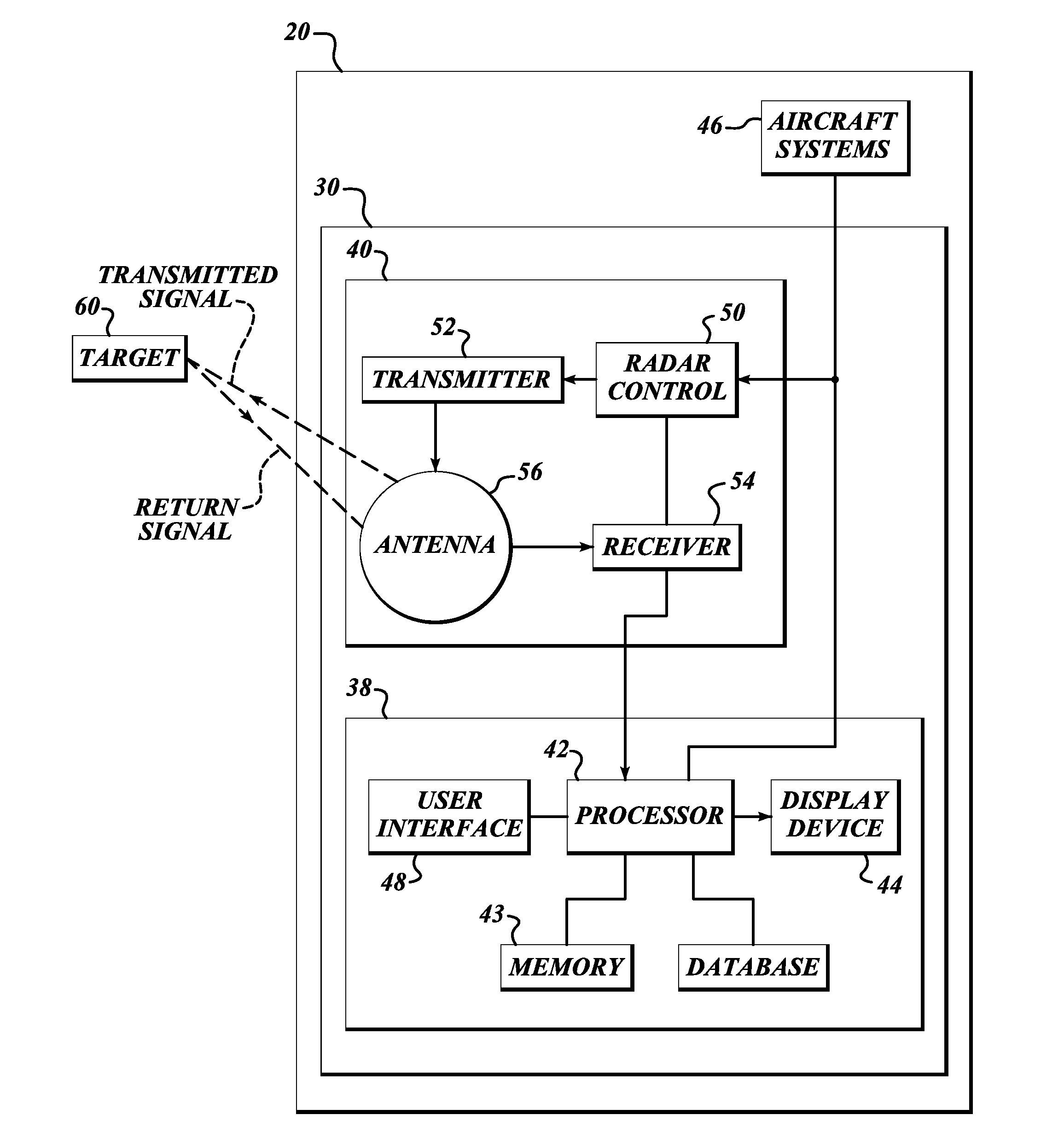
[0032]FIG. 3 illustrates an example system 30 for providing more accurate flight plan / path weather information on an aircraft 20. The system 30 includes a radar display system 38 that includes a weather radar system 40, a display processor 42, memory 43, a display device 44, and a user interface 48 coupled to the display processor 42. The aircraft 20 also includes other aircraft systems 46, such as an air data computer (ADC), that are in signal communication with the weather radar system 40 and the radar display system 38. The display processor 42 is electrically coupled to the radar system 40, the display device 44, the ADC, and the memory 43. The radar system 40 includes a radar controller 50, a transmitter 52, a receiver 54, an antenna 56, and an antenna controller 61. The radar controller 50 controls the transmitter 52 and the receiver 54 for performing the transmitting and receiving of signals through the antenna 56 based on the selected radar mode and other pilot inputs receiv...


PUM


Abstract

Systems and methods for improving relevant weather determination for aircraft at altitude. An exemplary system includes a weather radar component and memory that stores weather radar data in a three-dimensional (3D) buffer. A processor calculates vertically integrated reflectivity using the stored weather radar data at a predefined reference altitude at one or more locations from the aircraft. The processor then adjusts a lower boundary of a relevant weather envelope from a first value to a second value, if the vertically integrated reflectivity is greater than a predefined threshold. The range of the adjusted lower boundary of the envelope is associated with the weather radar data having the calculated vertically integrated reflectivity greater than the predefined threshold. A display device displays the weather radar data located within the envelope in a first manner and displays the weather radar data located outside of the envelope in a second manner.

Description

BACKGROUND OF THE INVENTION[0001]The RDR-4000 IntuVue® radar incorporates a volumetric, 3D buffer concept that enables several features not previously available in airborne weather radar. One of those features is the Automatic mode which provides a display of weather relevant to the intended aircraft flight path (either via data from a flight management system or inferred from present altitude, vertical speed and / or ground speed).[0002]Currently, the relevant weather is defined as a corridor (envelope) extending from 4000 ft above the intended aircraft flight path to 4000 ft below the aircraft intended flight path, with the following basic modifications:[0003]the lower boundary is limited to a maximum value of 25,000 ft MSL;[0004]the lower boundary is limited to a minimum value of 0 ft MSL (limit of the volumetric buffer);[0005]the upper boundary is limited to a maximum value of 60,000 ft MSL (limit of the volumetric buffer); and[0006]the upper boundary is limited to a minimum of 10...

Claims


Application Information

Patent Timeline
Patent Type & Authority Applications(United States)
IPC IPC(8): G01S13/95
CPCG01S13/953G01S7/04Y02A90/10
Inventor BUNCH, BRIAN P.CHRISTIANSON, PAUL
Owner HONEYWELL INT INC
Why Eureka
Try Eureka