Liquid crystal display device

a liquid crystal display and display device technology, applied in the field of liquid crystal display devices, can solve the problems of illumination light leakage, insufficient white peak luminance, and lesser white image sharpness, and achieve the effect of preventing luminance insufficiency

Inactive Publication Date: 2012-06-07
HITACHI CONSUMER ELECTRONICS CORP
View PDF0 Cites 51 Cited by
  • Summary
  • Abstract
  • Description
  • Claims
  • Application Information

AI Technical Summary

Benefits of technology

[0013]According to the present invention, it is possible to provide a liquid crystal display device that prevents luminance insufficiency attributing to leaking of illumination light between adjacent areas the black floating.

Problems solved by technology
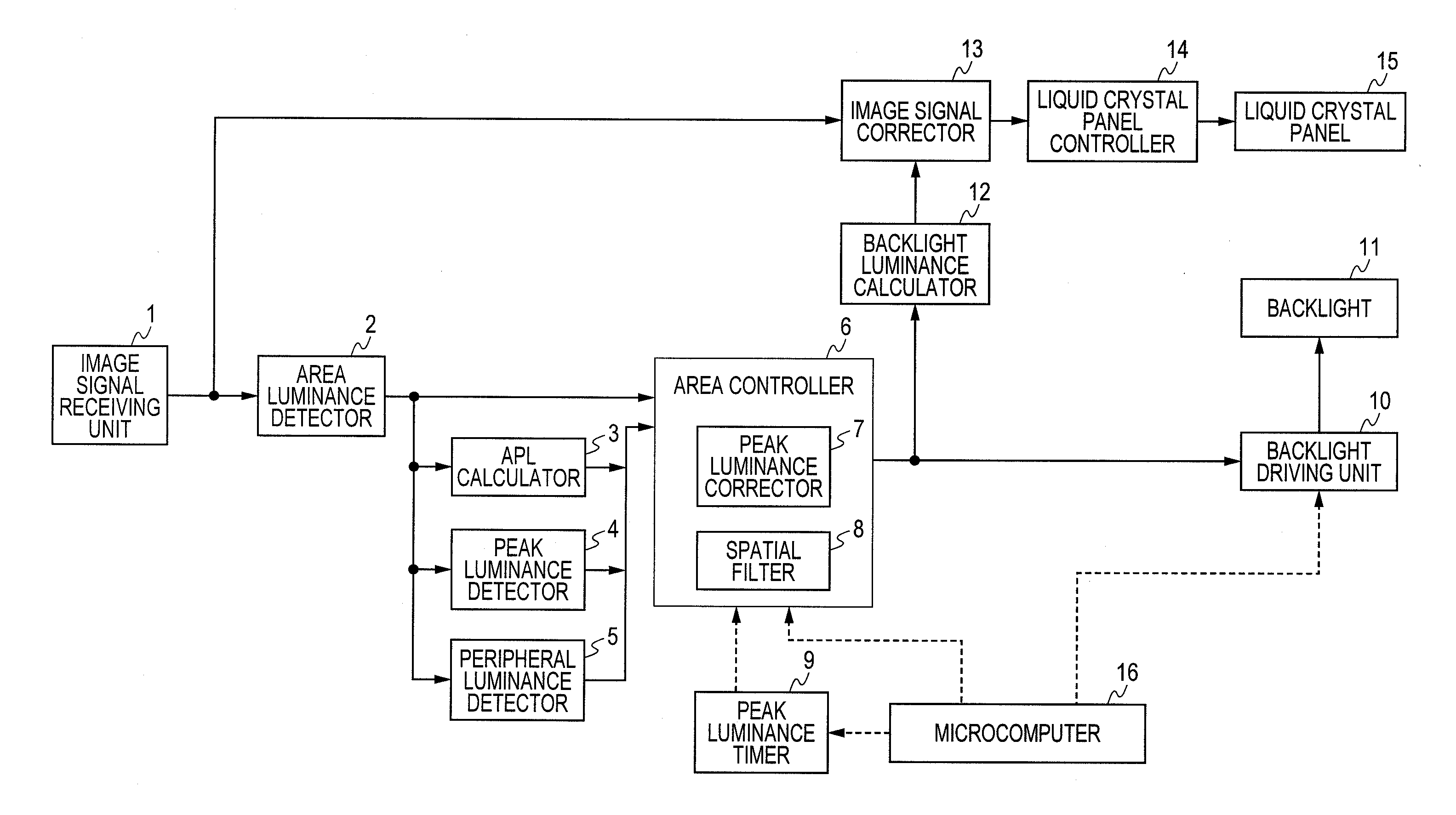
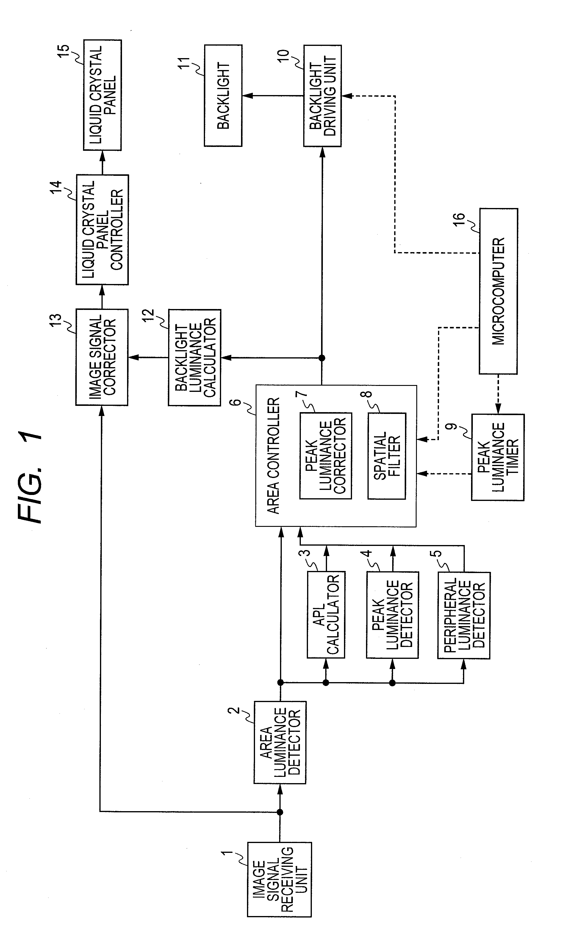
In addition to the aforementioned black floating, another problem with the area control is that white peak luminance is insufficient.
Specifically, when a white image (high-luminance peak part) is present only in a part of a black background (low luminance), the backlight luminance is insufficient for the white image, leading to the lesser sharpness of the white image.
On the other hand, when the luminance distribution in the screen is not uniform, the illumination light leaks only one way: from a high-luminance area to a low-luminance area.
As a result, when a white image and a black image are adjacent to each other, the illumination light leaks less from the black image (low-luminance area) into the white image (high-luminance area), leading to the insufficiency of the white image luminance.
This is because that the luminance of the black image is not sufficiently lowered due to the leaking of illumination light from the high-luminance area (white image) into the low-luminance area (black image), when a black image and a white image are located adjacent to each other.
Although the technique disclosed in JP-A-2008-51905 is effective for a problem caused by the contrast property of the liquid crystal panel, the technique does not solve a problem caused by leaking of illumination light between adjacent areas.

Method used


Image

  • Liquid crystal display device
  • Liquid crystal display device
  • Liquid crystal display device

Examples


first embodiment

[0033]In the first embodiment, a luminance control for a high-luminance area is described in which a high-luminance image is displayed in a low-luminance background image.

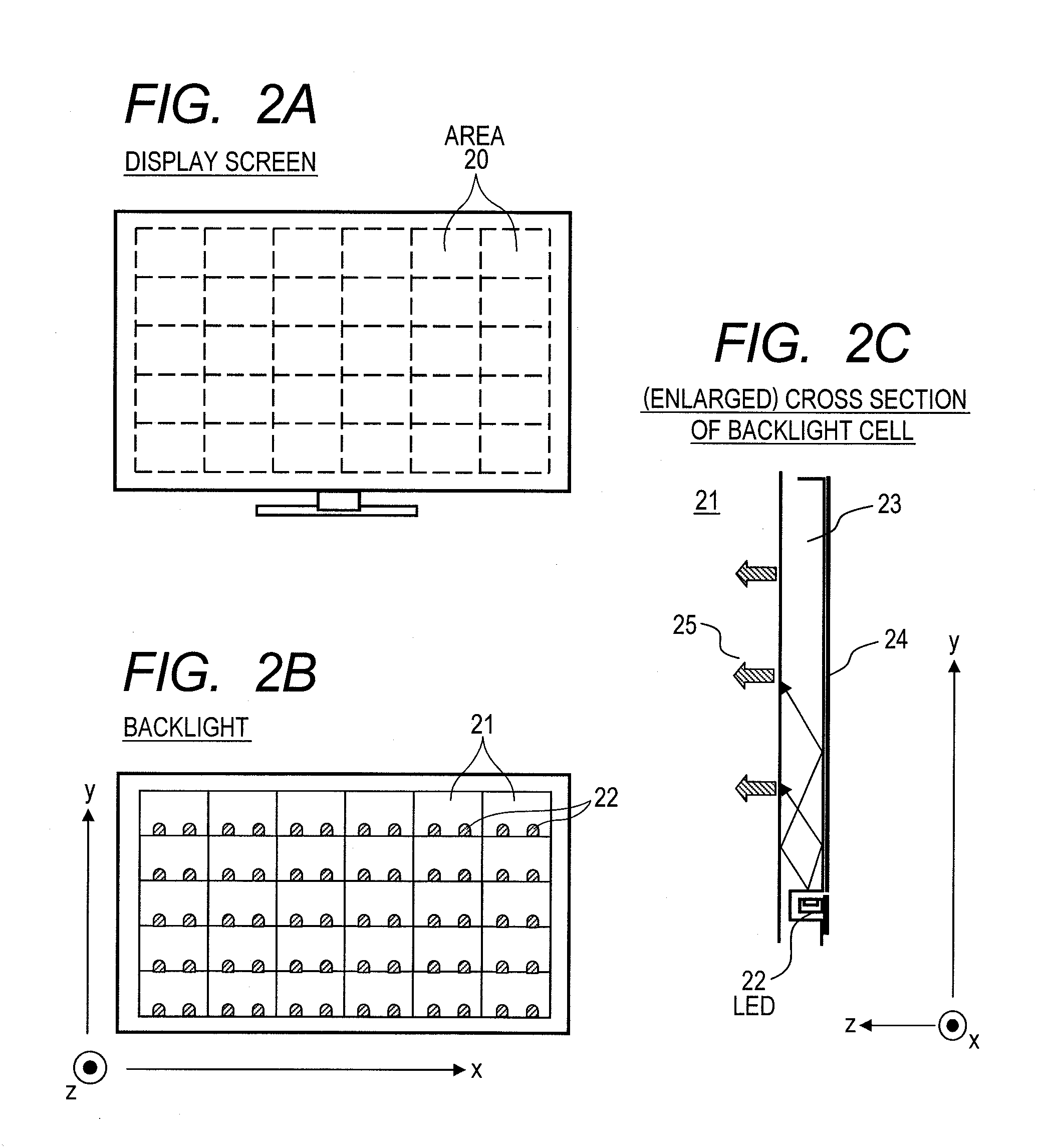
[0034]FIG. 3 is a diagram illustrating an example of the display screen on which the luminance control according to the present embodiment is performed. FIG. 3 illustrates the case in which a single high-luminance area is solely present.

[0035]The display screen is divided into 12×6 areas. A high-luminance image (white image) is displayed in a low-luminance background image (black image) on the display screen. It is assumed that the high-luminance image is present in a single area B. The area B is hereinafter called a “peak luminance area,” while areas C in which the low-luminance image is displayed and located adjacent to the area B are hereinafter called “peripheral areas.” In this example, four peripheral areas C are present. Light does not leak from the area B into areas diagonally located by the area B (or too ...

second embodiment

[0060]In the second embodiment a luminance control for a low-luminance area is described in which a low-luminance image is displayed in a high-luminance background image.

[0061]FIG. 8 is a diagram illustrating an example of the display screen on which the luminance control according to the present embodiment is performed. FIG. 8 illustrates the case in which a single low-luminance area is solely present.

[0062]The display screen is divided into 12×6 areas. The low-luminance image (black image) is displayed in the high-luminance background image (white image). It is assumed that the low-luminance image is present in a single area E. The area E is hereinafter called a “peak luminance area,” while areas F in which the high luminance image is displayed and located adjacent to the peak luminance area E are hereinafter called “peripheral areas.” In this example, four peripheral areas F are present.

[0063]According to the conventional area control, a backlight luminance level of the area E is...


PUM

PropertyMeasurementUnit
thresholdaaaaaaaaaa
thresholdaaaaaaaaaa
thresholdaaaaaaaaaa

Abstract

According to the present invention, area control of a liquid crystal display device prevents luminance insufficiency attributing to leaking of illumination light between adjacent areas. A peak luminance detector detects a peak luminance area in which a luminance level is equal to or higher than a first threshold. A peripheral luminance detector detects luminance levels of peripheral areas located adjacent to the peak luminance area. When the average of the luminance levels of the peripheral areas is equal to or lower than a second threshold, a peak luminance corrector increases a light source luminance level of a backlight cell that corresponds to the peak luminance area.

Description

CLAIM OF PRIORITY[0001]The present application claims priority from Japanese patent application serial No. JP 2010-272586, filed on Dec. 7, 2010, the content of which is hereby incorporated by reference into this application.BACKGROUND OF THE INVENTION[0002](1) Field of the Invention[0003]The present invention relates to a liquid crystal display device that has a backlight for illuminating, from a back surface of a liquid crystal panel, the liquid crystal panel for displaying an image, in which luminance of the backlight is controlled according to an image signal for displaying.[0004](2) Description of the Related Art[0005]A liquid crystal display device is different from light-emitting display devices such as a CRT or plasma display panel in that it includes a non-light-emitting liquid crystal panel (light-transmissive optical modulation element) and a backlight. The backlight is arranged on the back surface of the liquid crystal panel and illuminates the liquid crystal panel. The ...

Claims


Application Information

Patent Timeline
Patent Type & Authority Applications(United States)
IPC IPC(8): G09G5/00
CPCG09G3/3426G09G3/3648G09G2360/16G09G2330/021G09G2320/0646
Inventor IWASA, HIROSHIKUBOTA, HIDENAO
Owner HITACHI CONSUMER ELECTRONICS CORP
Why Eureka
Try Eureka