Plug-in device for an optical cable

a plug-in device and optical cable technology, applied in the field of cable entry, can solve the problems of difficult unlocking and relatively difficult to fit in the field of cable entries known from the prior art, and achieve the effect of simple manner

Active Publication Date: 2012-06-07
HUBERSUHNER AG
View PDF2 Cites 28 Cited by
  • Summary
  • Abstract
  • Description
  • Claims
  • Application Information

AI Technical Summary

Benefits of technology

[0012]One object of the invention consists in disclosing a cable entry or a connector which

Problems solved by technology

Whilst being plugged into a socket provided for this purpose, the locking arm is moved downwards, with the result that the locking shoulders snap into cutouts provided for this purpose in the mating piece.
In particular in difficult spatial conditions, unlocking is di

Method used


Image

  • Plug-in device for an optical cable
  • Plug-in device for an optical cable
  • Plug-in device for an optical cable

Examples


Embodiment Construction

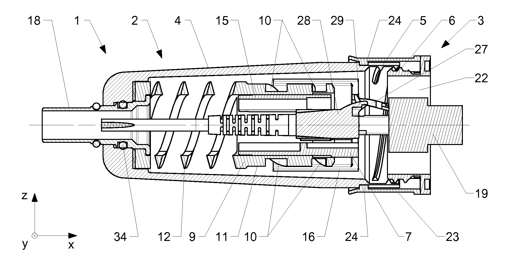
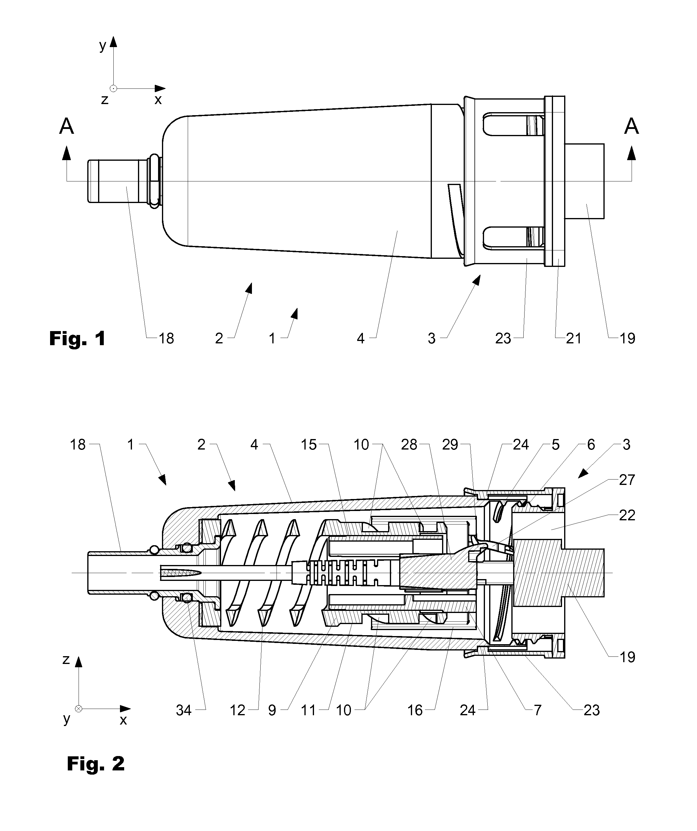
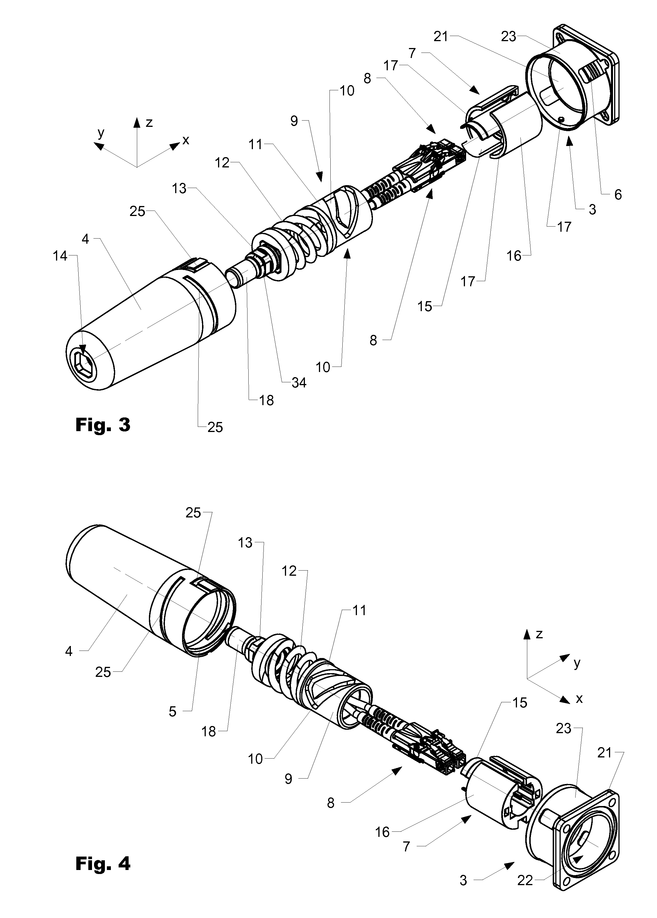
[0040]FIG. 1 shows a cable entry 1 with a cable-side plug-in part 2 and a housing-side flange 3 in a plan view in the operatively connected state. FIG. 2 shows a sectional illustration through the cable entry 1 along the section line AA. FIG. 3 shows the cable entry 1 in a perspective, exploded illustration at an angle from the front and from above, and FIG. 4 shows the cable entry 1 in a perspective, exploded illustration at an angle from the rear and from above. FIG. 5 shows the cable-side plug-in part 2 and the housing-side flange 3 in the disassembled state. FIG. 6 shows a control part 9 and a spring 12 in a side view. FIG. 7 shows a holder 7 and two connectors 8 in a perspective illustration at an angle from the front and from above prior to fitting.

[0041]The plug-in part 2 has a locking sleeve 4 with an inner thread 5, which interacts with an outer thread 6 of the flange 3 in the coupled state of the cable entry 1 (cf. FIG. 2). Alternatively or in addition, further operative c...


PUM


Abstract

The invention relates to a cable gland (1) having a flange (3) and a plug-in part (2) suited for an operational connection to the flange (3). The plug-in part (2) comprises a locking sleeve (4), and a fastener (7) for a connector (8), said fastener being operatively connected to said locking sleeve by way of a control slide (10). The control slide (10) is configured such that a rotation of the locking sleeve (4) around the longitudinal axis (x) of the plug-in part (2) results in an axial displacement of the fastener (7) in a longitudinal direction.

Description

BACKGROUND OF THE INVENTION[0001]1. Field of the Invention[0002]The invention relates to a cable entry, for example for connecting a fiberoptic cable to a remote radio head (RRH) in a mobile radio antenna.[0003]In mobile communication systems, so-called remote radio heads (RRHs) are used. Said remote radio heads permit a greater distance between the base station and the antenna. The RRHs are generally connected to the base station via fiberoptic lines (fiberoptic cables). In order that the fiberoptic lines can be connected in a simple manner using the connectors fixed thereto, cable entries with holding devices in front of them are used.[0004]2. Discussion of Related Art[0005]Cable entries are known from the prior art. Said cable entries comprise an appliance-side flange with a coupling thread, a fitting opening and a cable-side plug-in part with a union nut, which can be operatively connected to the coupling thread. The flange is fastened on the outside to a housing of an RRH. LC c...

Claims


Application Information

Patent Timeline
IPC IPC(8): G02B6/00
CPCG02B6/3879H01R13/625G02B6/3897G02B6/3891G02B6/3893
Inventor GREUB, DANIELVOLKER, MICHAELBOLLHALDER, LEO
Owner HUBERSUHNER AG
Why Eureka
Try Eureka