Transponder for an optical communications system and optical communications system

a technology of optical communication system and optical communication system, applied in the direction of fibre transmission, distortion/dispersion elimination, electrical apparatus, etc., can solve the problems of requiring even more complexity, unable to realize digital equalization in the receiver, and difficult to implement a high-speed asic for 100 gbit/s pdm-qpsk transmission, etc., to achieve the effect of improving the transmission performan

Inactive Publication Date: 2012-06-07
HUAWEI TECH CO LTD
View PDF7 Cites 14 Cited by
  • Summary
  • Abstract
  • Description
  • Claims
  • Application Information

AI Technical Summary

Benefits of technology

[0041]According to some implementations, the transmission performance may be highly improved by optimizing the transmitter, in particular its pre-equalizer.
[0042]According to some implementations,

Problems solved by technology

Given the high data rates, it may be challenging to implement a high-speed ASIC for 100 Gbit/s PDM-QPSK transmission.
Higher-order modulation formats like 16 QAM may require even more complexity, such that di

Method used


Image

  • Transponder for an optical communications system and optical communications system
  • Transponder for an optical communications system and optical communications system
  • Transponder for an optical communications system and optical communications system

Examples


first embodiment

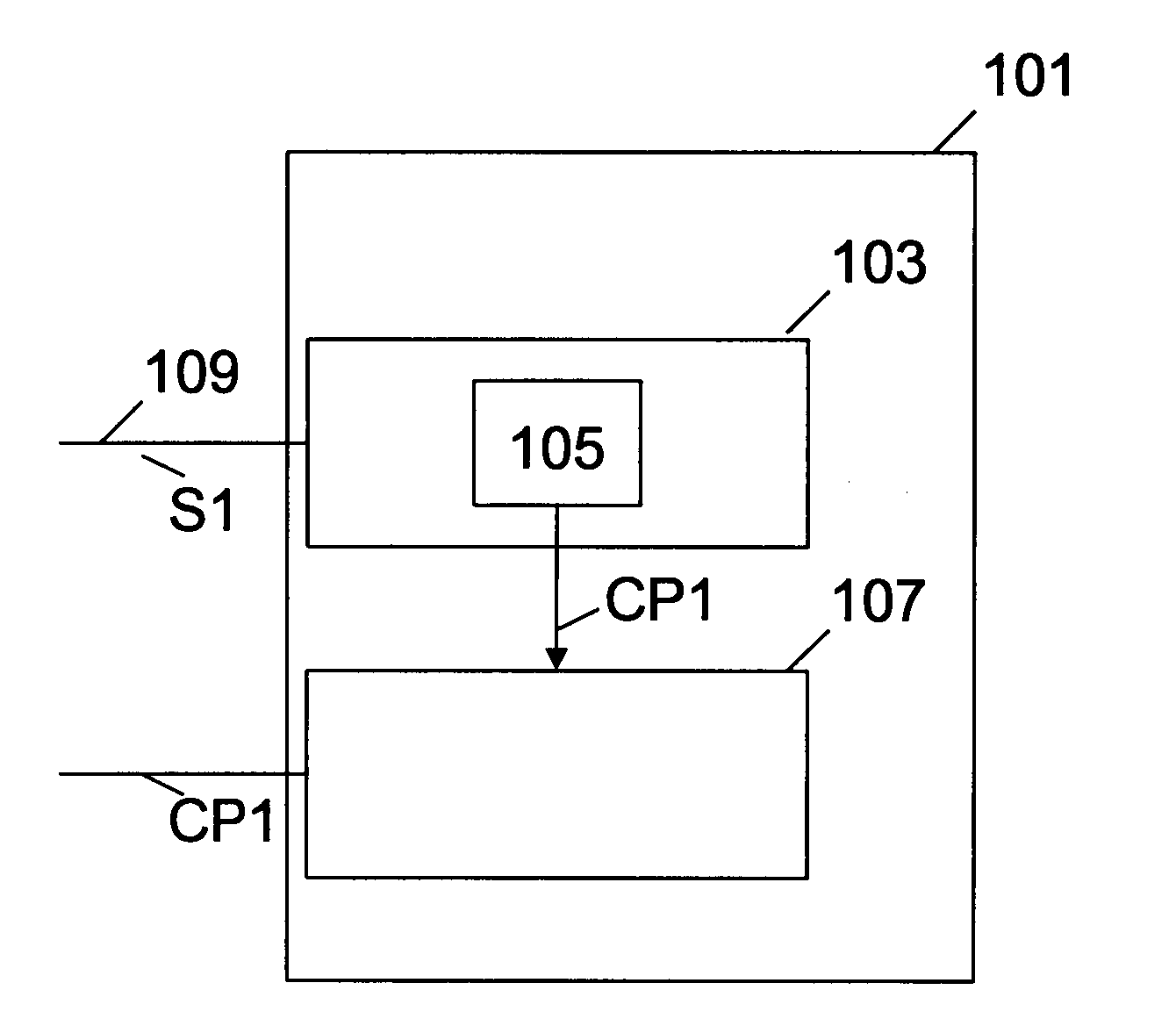
[0051]In FIG. 1, a transponder 101 of an optical communications system is shown. The transponder 101 may be called first transponder in the following. The first transponder 101 has a first receiver 103 having a monitor 105 and a first transmitter 107.

[0052]The first receiver 103 is adapted to receive a first signal S1. The first signal S1 is transmitted by a second transmitter of a further transponder over an optical channel 109.

[0053]The monitor 105 is adapted to provide at least one channel parameter CP1 describing the optical channel 109 in dependence on the received first signal S1.

[0054]Further, the first transmitter 107 is adapted to transmit the at least one first channel parameter CP1 to the further transponder for adjusting the pre-equalizer of the further transponder.

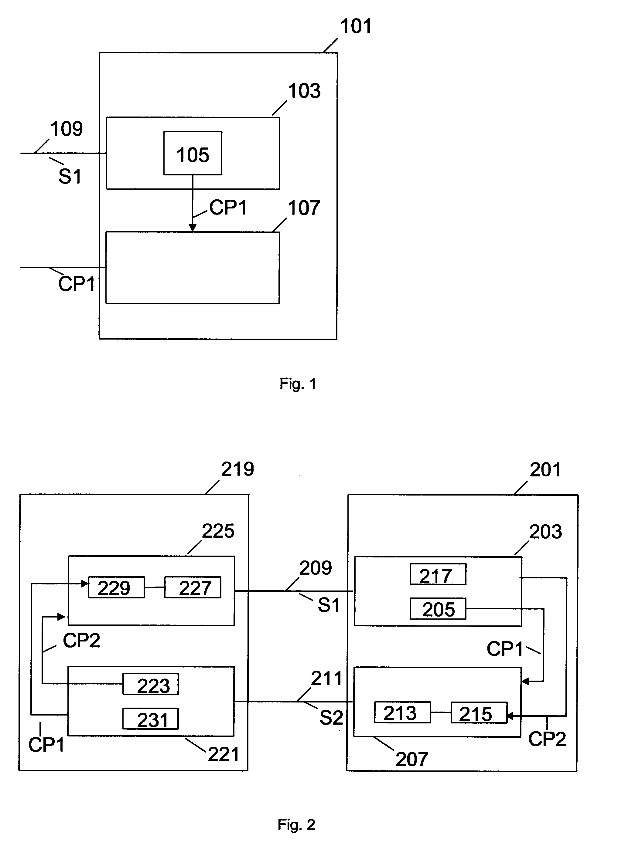
[0055]In FIG. 2, an embodiment of an optical communications system is depicted. The optical communications system has a first transponder 201 which is exemplarily embodied as the transponder 101 of FIG. 1. The...

second embodiment

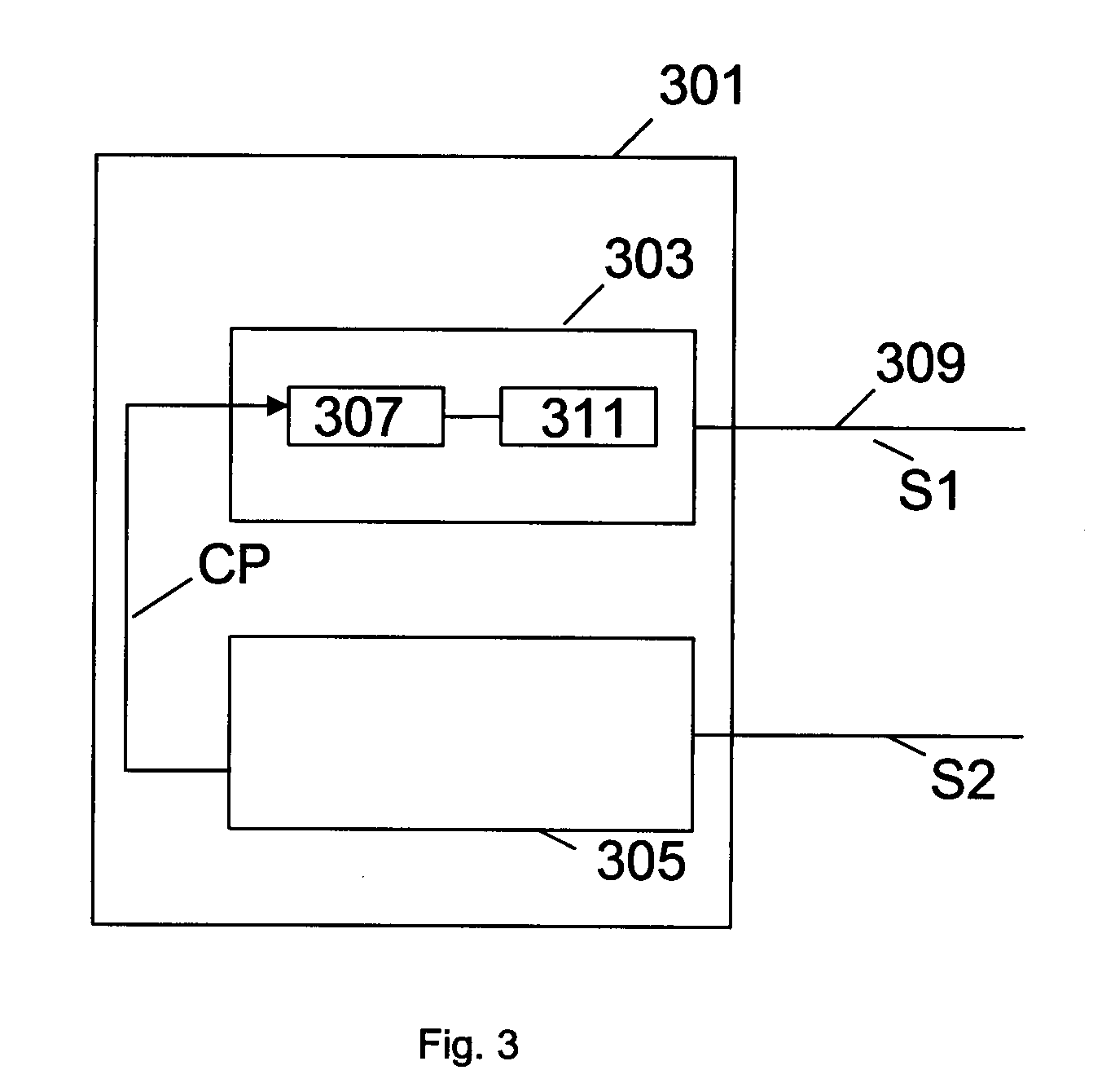
[0065]FIG. 3 shows a transponder 301 for an optical communications system. The transponder 301, in the following also called first transponder 301, has a first transmitter 303, a first receiver 305 and an adjuster 307.

[0066]The first transmitter 303 is adapted to transmit a first signal S1 to a second receiver of a second transponder over an optical channel 309. The first transmitter 303 may have a pre-equalizer 311 for pre-equalizing the first signal S1.

[0067]The first receiver 305 may be adapted to receive a second signal S2 transmitted by a second transmitter of the second transponder. The second signal S2 may include at least one channel parameter CP describing the optical channel 309 and being generated in dependence on the first signal S1. Further, the adjuster 307 may be adapted to adjust the pre-equalizer 311 in dependence on the received at least one channel parameter CP.

[0068]FIG. 4 illustrates an embodiment of a method for adjusting a pre-equalizer in an optical communica...


PUM


Abstract

A transponder is adapted to communicate with a further transponder over at least one optical channel. The transponder comprises a first receiver having a monitor and a first transmitter. The first receiver is configured to receive a first signal transmitted by a second transmitter of the further transponder over the optical channel. The monitor is configured to provide at least one channel parameter describing the optical channel in dependence on the received first signal. The first transmitter is configured to transmit the at least one channel parameter to the further transponder for adjusting a pre-equalizer of the further transponder.

Description

CROSS-REFERENCE TO RELATED APPLICATION[0001]This application is a continuation of International Application No. PCT / CN2010 / 0751522, filed on Jul. 14, 2010, entitled “Transponder for an optical communications system and optical communications system,” which is hereby incorporated herein by reference.BACKGROUND OF THE INVENTION[0002]The present invention relates to communications over optical communications systems having at least one optical channel.[0003]Conventional transponders for optical communication include a transmitter and a receiver in one device. Especially in long-haul transmission, two transponders define a bidirectional link, wherein the data is transmitted between the transmitter and the receiver in the respective device. The two optical paths or channels of the bidirectional link do not necessarily need to be in the same wavelength or the same path.[0004]Further to meet demands for transmission capacity, the spectral efficiency has to be increased with higher-order mo...

Claims


Application Information

Patent Timeline
IPC IPC(8): H04B10/00H04B10/2507H04B10/2513H04B10/2569
CPCH04B10/25137H04B10/2572H04B10/2569
Inventor HAUSKE, FABIAN NIKOLAUS
Owner HUAWEI TECH CO LTD
Why Eureka
Try Eureka