
System-level emulation/verification system and system-level emulation/verification method

a verification system and system-level technology, applied in the field of circuit design verification system, can solve the problems of reducing the test period, reducing the test cost, and increasing the human resource cost and the required design period

Inactive Publication Date: 2012-06-07
FARADAY TECH CORP
View PDF8 Cites 14 Cited by
  • Summary
  • Abstract
  • Description
  • Claims
  • Application Information

AI Technical Summary

Problems solved by technology

With the advance of electronic technology, modern circuit systems are becoming highly complex and large-sized.
This results in the need to test functionality of a whole circuit system as quickly as possible and to retrench the testing costs.
The human resource costs and the required design period are significantly increased in order to provide this individual testing platform corresponding to the individual circuit system.
Even if the emulation / verification platforms can be provided with less effort and expenditure, the simulating costs will be increased due to the greatly used Field Programmable Gate Arrays (FPGAs) required by the emulation / verification platforms.
Moreover, the FPGAs corresponding to the emulation / verification platforms cannot be operated at a speed as fast as the operating speed of substantiated circuits after the tape-out operations.
In other words, since the operating speed of FPGAs, or so called “silicon-level speeds”, are much slower than the real speed of the substantiated circuits after the tape-out operations, the mismatch between the emulating / verifying results of the emulation / verification platforms and substantiated circuit systems is unavoidable.
Furthermore, each of the existing emulation / verification platforms may need their own particular Printed Circuit Boards (PCBs) or Evaluation Boards (EVB) for emulating / verifying specific circuit designs which will further raise the circuit costs and increase required time.
In addition, when the circuit system is adjusted, the corresponding emulation / verification systems with many FPGAs need to repeatedly emulate / verify at different frequencies, which further extends the required time.

Method used


Image

  • System-level emulation/verification system and system-level emulation/verification method
  • System-level emulation/verification system and system-level emulation/verification method
  • System-level emulation/verification system and system-level emulation/verification method

Examples


Embodiment Construction

[0017]Certain terms are used throughout the description and following claims to refer to particular components. As one skilled in the art will appreciate, manufacturers may refer to a component by different names. This document does not intend to distinguish between components that differ in name but not function. In the following description and in the claims, the terms “include” and “comprise” are used in an open-ended fashion, and thus should be interpreted to mean “include, but not limited to . . . ” Also, the term “couple” is intended to mean either an indirect or direct electrical connection. Accordingly, if one device is coupled to another device, that connection may be through a direct electrical connection, or through an indirect electrical connection via other devices and connections.

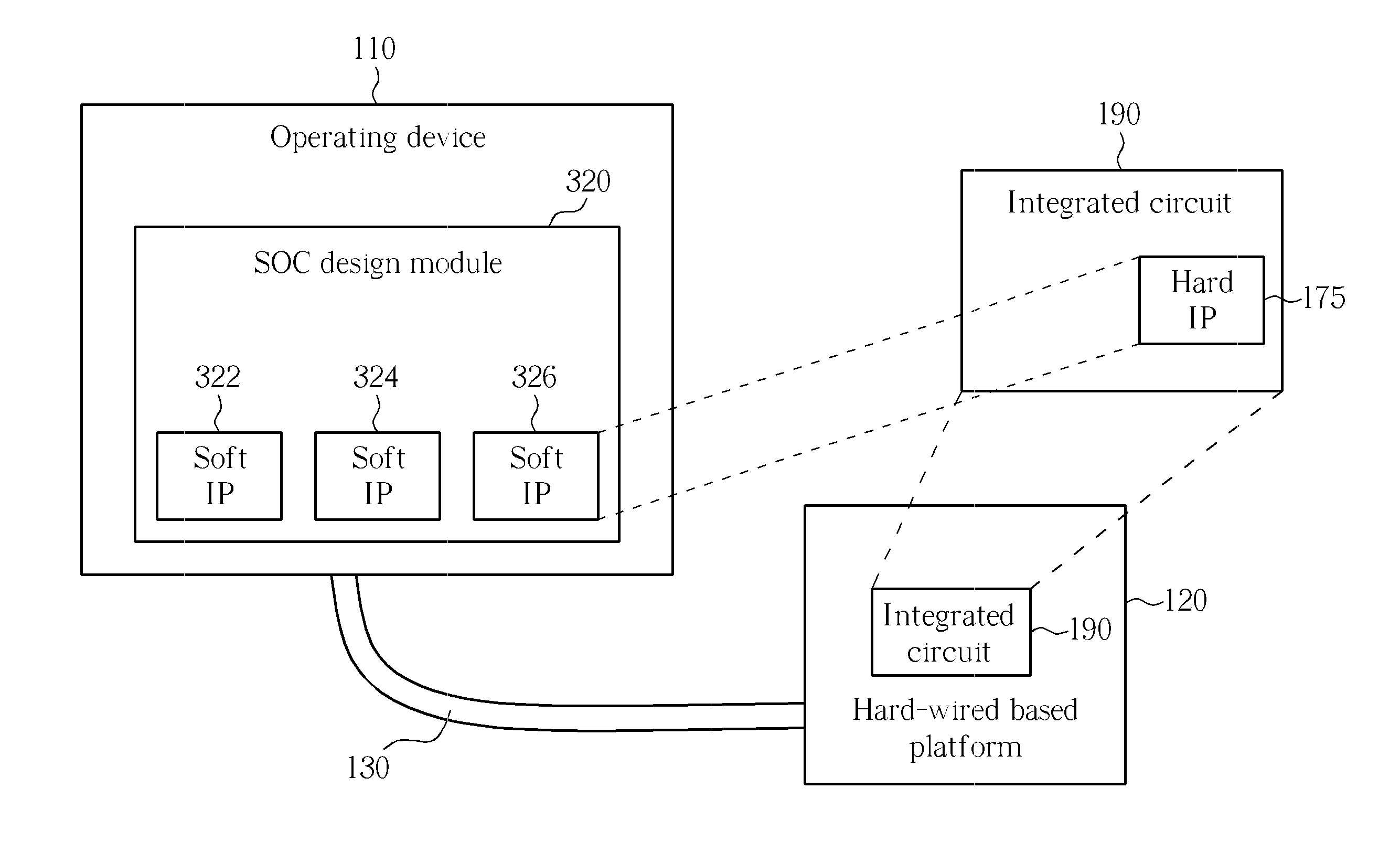
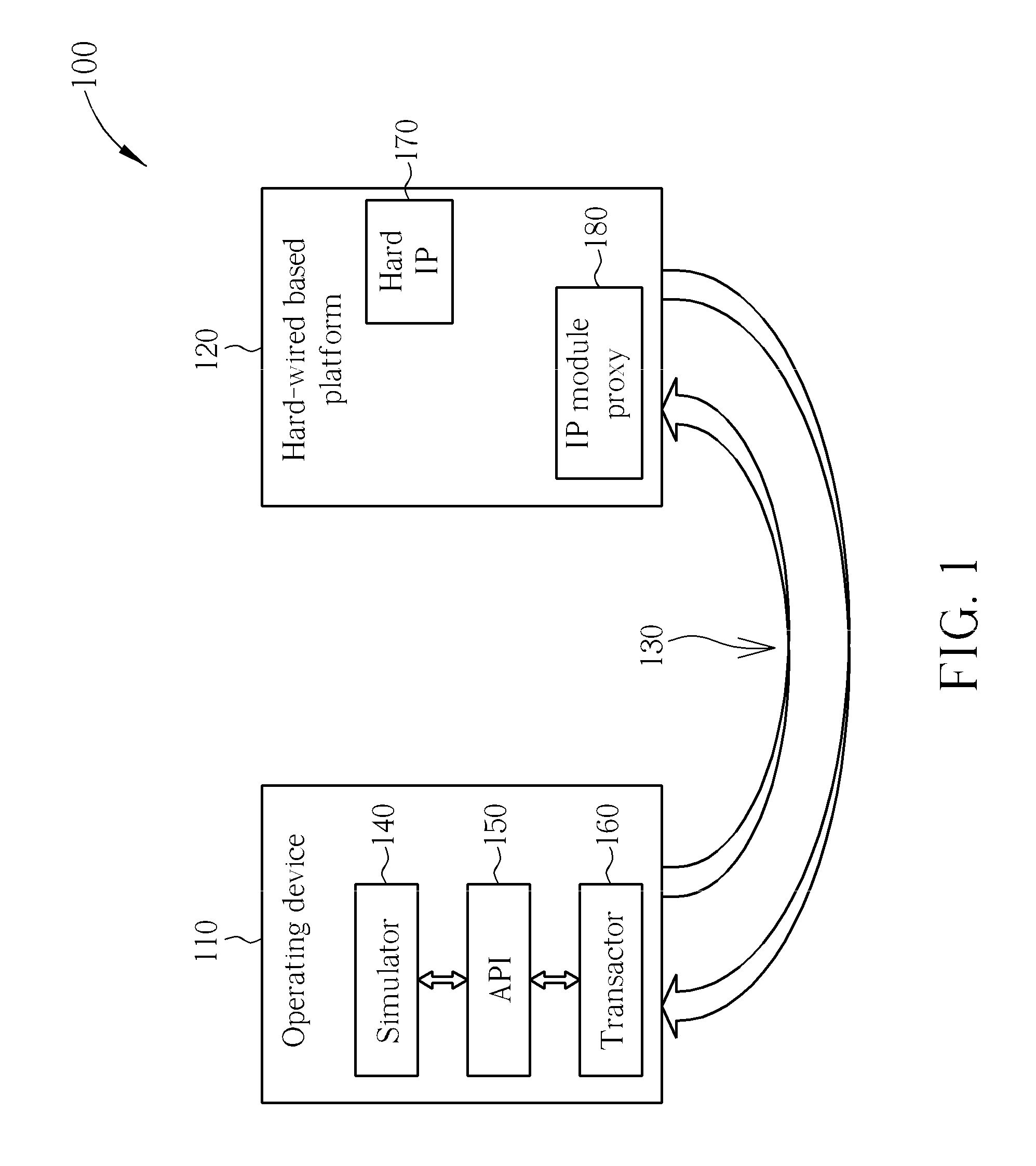
[0018]Please refer to FIG. 1. FIG. 1 is a diagram illustrating a system-level emulation / verification system according to a first exemplary embodiment of the present invention. As shown in FIG....


PUM


Abstract

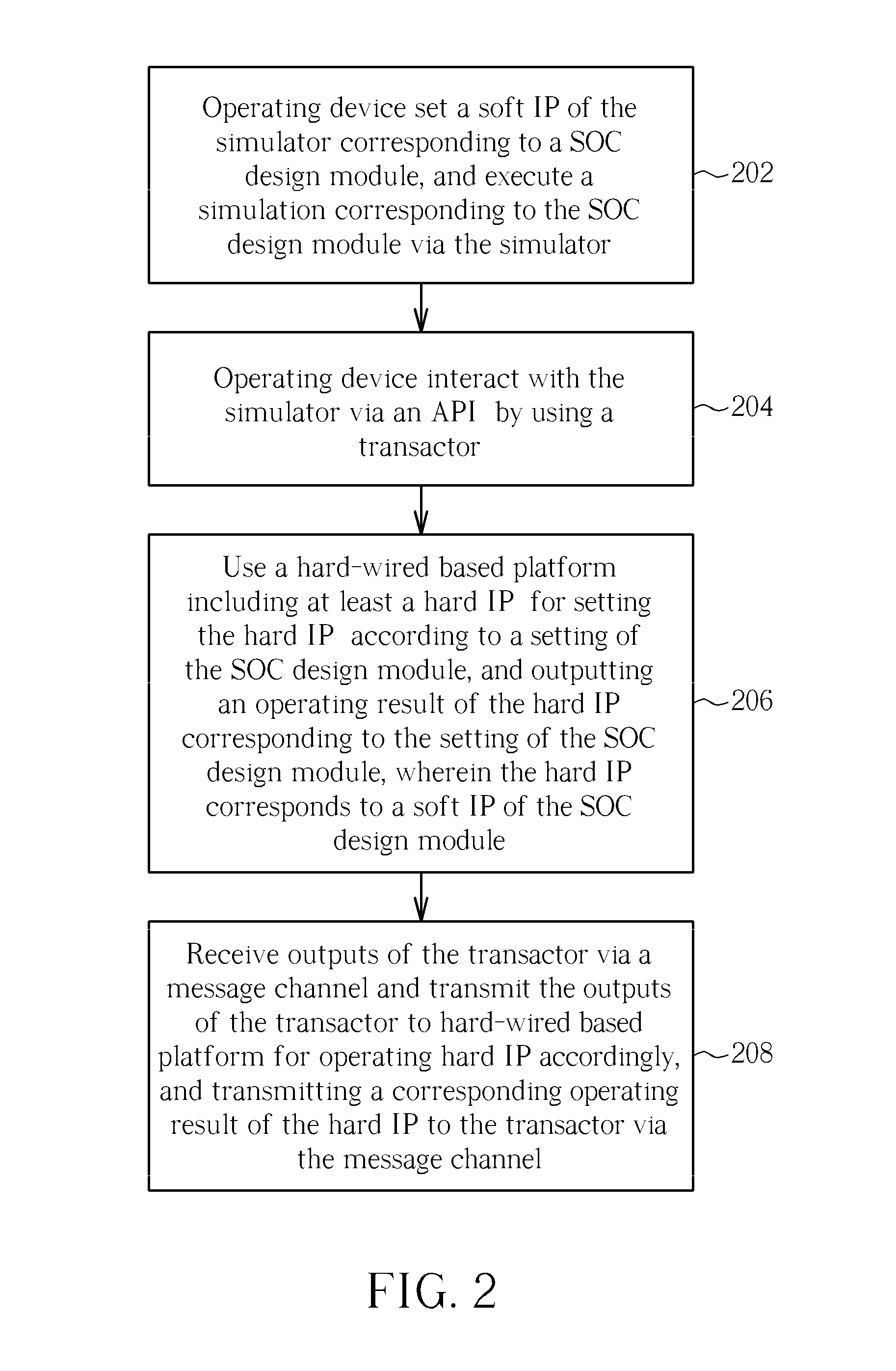
A system-level emulation / verification system includes an operating device for using a simulator to set soft intellectual properties (soft IPs) corresponding to a System-on-Chip (SOC) design module, executing a simulation corresponding to the SOC design module, and using a transactor to interact with the simulator via an Application Programming Interface (API); and a hard-wired based platform, including a hard IP corresponding to a soft IP of the SOC design module, wherein the hard-wired based platform sets the hard IP according to a setting of the SOC design module, and outputs an operating result of the hard IP corresponding to the setting of the SOC design module. The hard-wired based platform executes an IP model proxy for receiving an output of the transactor, transmitting the output to the hard-wired platform for controlling the operation of the hard IP, and transmitting the operating result to the transactor executed by the operating device.

Description

BACKGROUND OF THE INVENTION[0001]1. Field of the Invention[0002]The present invention relates to a circuit design emulation / verification system, and more particularly, to an emulation / verification system which can execute system-level emulations and verifications of a whole circuit system before a tape-out operation of the whole circuit system is executed.[0003]2. Description of the Prior Art[0004]With the advance of electronic technology, modern circuit systems are becoming highly complex and large-sized. This results in the need to test functionality of a whole circuit system as quickly as possible and to retrench the testing costs. Conventionally, circuit designers can only emulate and verify the whole circuit system to ensure system-level functionality after the hardware circuits corresponding to the whole circuit system have been substantiated, allowing the corresponding software to then be developed.[0005]According to the teachings of U.S. Pat. No. 4,901,259, for speeding up t...

Claims


Application Information

Patent Timeline
Patent Type & Authority Applications(United States)
IPC IPC(8): G06F17/50
CPCG06F2217/66G06F17/5027G06F30/331G06F2115/08
Inventor HUANG, CHENG-YENCHEN, CHENG-CHIEN
Owner FARADAY TECH CORP
Learn More