Helmet and visor locking mechanism

a technology of locking mechanism and visor, which is applied in the field of helmet locking mechanism, can solve the problems of many helmets opening in freefall, helmets fixed to helmets that do not allow the wearer to open the face shield, and the use of known motorcycle type face shield lock mechanism often fails to remain closed during use, so as to achieve convenient holding

Active Publication Date: 2012-06-14
COOKIE COMPOSITES
View PDF34 Cites 10 Cited by
  • Summary
  • Abstract
  • Description
  • Claims
  • Application Information

AI Technical Summary

Benefits of technology

[0019]The visor Locking plate acts to retain the visor between itself and the hub. The visor locking plate's shape acts as a f

Problems solved by technology

These fixed visor helmets did not allow the wearer to open the face shield while being worn.
Flip up visor helmets entered the market in approximately 1995, however the mechanisms used to keep the face shield locked while traveling at

Method used


Image

  • Helmet and visor locking mechanism
  • Helmet and visor locking mechanism
  • Helmet and visor locking mechanism

Examples


Embodiment Construction

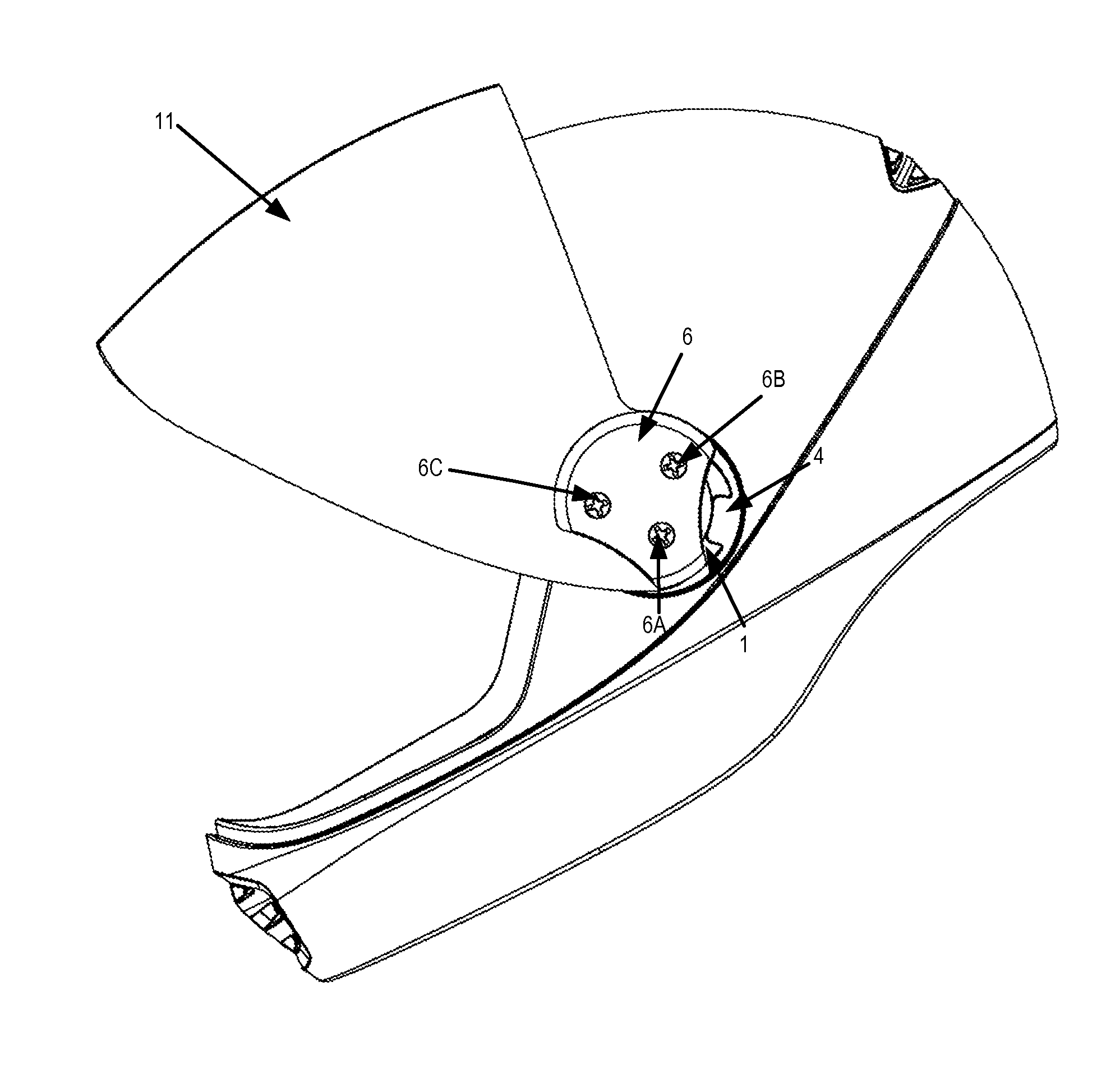
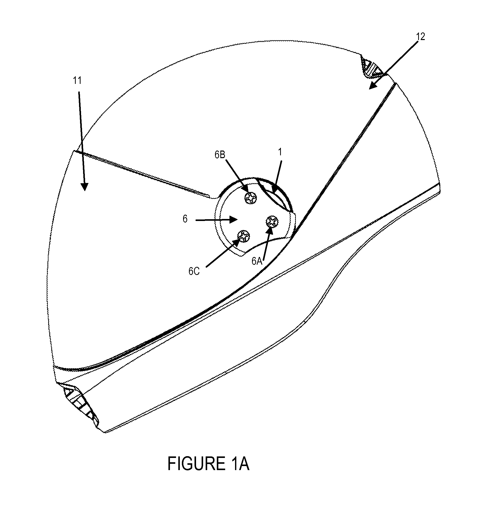
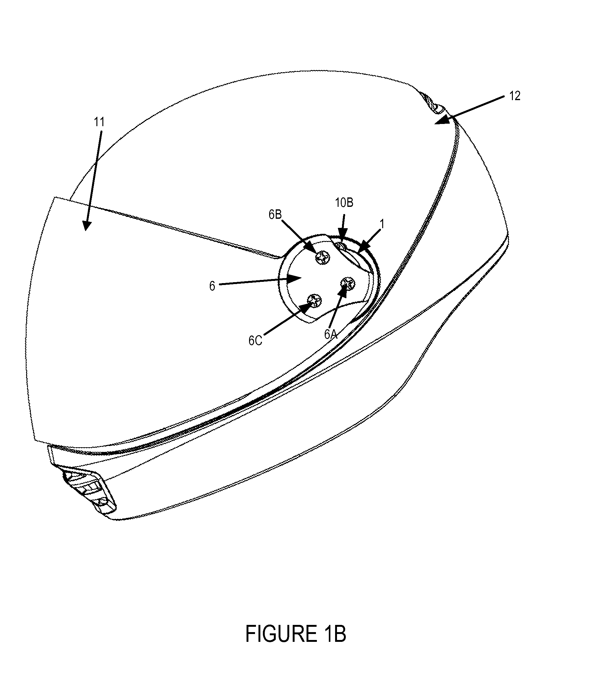
[0031]Referring to the drawings, FIG. 1A shows a helmet assembly including a helmet 12 with a visor 11 (or face shield) in a closed, lowered, or fully down position with the visor pushed fully back thereby placing the visor lock assembly in a locked position. Visor locking plate 6, sometimes referred to as a gripping member, can be grasped by the wearer of helmet 12 and moved laterally forward (moving visor 11 away from the face of the wearer), thereby unlocking the locking mechanism. FIG. 1B shows the helmet assembly of FIG. 1 with the visor pulled forward so that it is in the unlocked position and ready for rotation. Screws 6A, 6B, and 6C, shown in FIGS. 1A and 1B, advantageously mount the visor locking plate 6 to the hub which can be seen in FIG. 2, while allowing the hub to rotate around body 1. Screw 10B which is slightly visible is illustrated more clearly in FIG. 3 and is used, along with another screw, to mount body 1 onto helmet 12.

[0032]FIG. 2 shows the helmet of FIGS. 1A ...


PUM


Abstract

A visor locking assembly alone or in combination with a helmet shell and visor. The visor locking assembly is attached to said shell and is used to mount the visor in a manner that allows the visor to be locked in a desired position. The visor locking assembly is configured to prevent the visor from being moved from a fully lowered position to a raised position unless the visor is displaced laterally forward away from the face of the wearer of the helmet. The locking assembly further comprises a body and a rotatable hub, wherein the body comprises a cavity, and wherein the cavity further comprises a protrusion on the wall of the cavity, and wherein the rotatable hub comprises a recess formed along the circumference of the hub. The hub is positioned to rotate within the cavity, and the hub is prevented from rotational movement when the protrusion is positioned within (engaged with) the recess. When the hub is displaced laterally within the cavity away from the protrusion, the hub becomes rotatable. A spring is attached to the hub inhibiting said displacement. The system may comprise a single visor locking assembly or two visor locking assemblies on a helmet. If two assemblies are utilized, the visor cannot be raised from a fully lowered position unless both assemblies are unlocked.

Description

RELATED APPLICATION[0001]The present application claims the benefit of U.S. Provisional Patent Application Ser. No. 61 / 421,507, filed Dec. 9, 2010 which is hereby expressly incorporated by reference in its entirety.FIELD OF THE INVENTION[0002]The invention relates to visor locking mechanisms suitable for use on helmets and, more particularly, to visor locking mechanisms which lock in a reliable manner and are suitable for a wide range of applications including, e.g., skydiving and / or motor cycle helmets.BACKGROUND OF THE INVENTION[0003]Full-face skydiving helmets with fixed face visors were developed and entered the market in the early 1990s. These fixed visor helmets did not allow the wearer to open the face shield while being worn. Flip up visor helmets entered the market in approximately 1995, however the mechanisms used to keep the face shield locked while traveling at speeds of, for example, +300 km / hr were rudimentary and resulted in many visors inadvertently opening during fr...

Claims


Application Information

Patent Timeline
IPC IPC(8): A42B3/04A42B3/22
CPCA42B3/223
Inventor HUNT, JEREMYCOOKE, JASON
Owner COOKIE COMPOSITES
Why Eureka
Try Eureka