Axial Flux Permanent Magnet Brushless Machine

Inactive Publication Date: 2012-06-14
HITACHI LTD
View PDF27 Cites 23 Cited by
  • Summary
  • Abstract
  • Description
  • Claims
  • Application Information

AI Technical Summary

Benefits of technology

[0011]Accordingly, the object of the present invention is to provide an axial gap type rotating electrical machine of a double rotor construction, in which the re

Problems solved by technology

Moreover, since the variable gap mechanism is complicated, accordingly there is a possibility that the construction of the rotating electrical machine may become complicated in order to ensure good streng

Method used


Image

  • Axial Flux Permanent Magnet Brushless Machine
  • Axial Flux Permanent Magnet Brushless Machine
  • Axial Flux Permanent Magnet Brushless Machine

Examples


Example

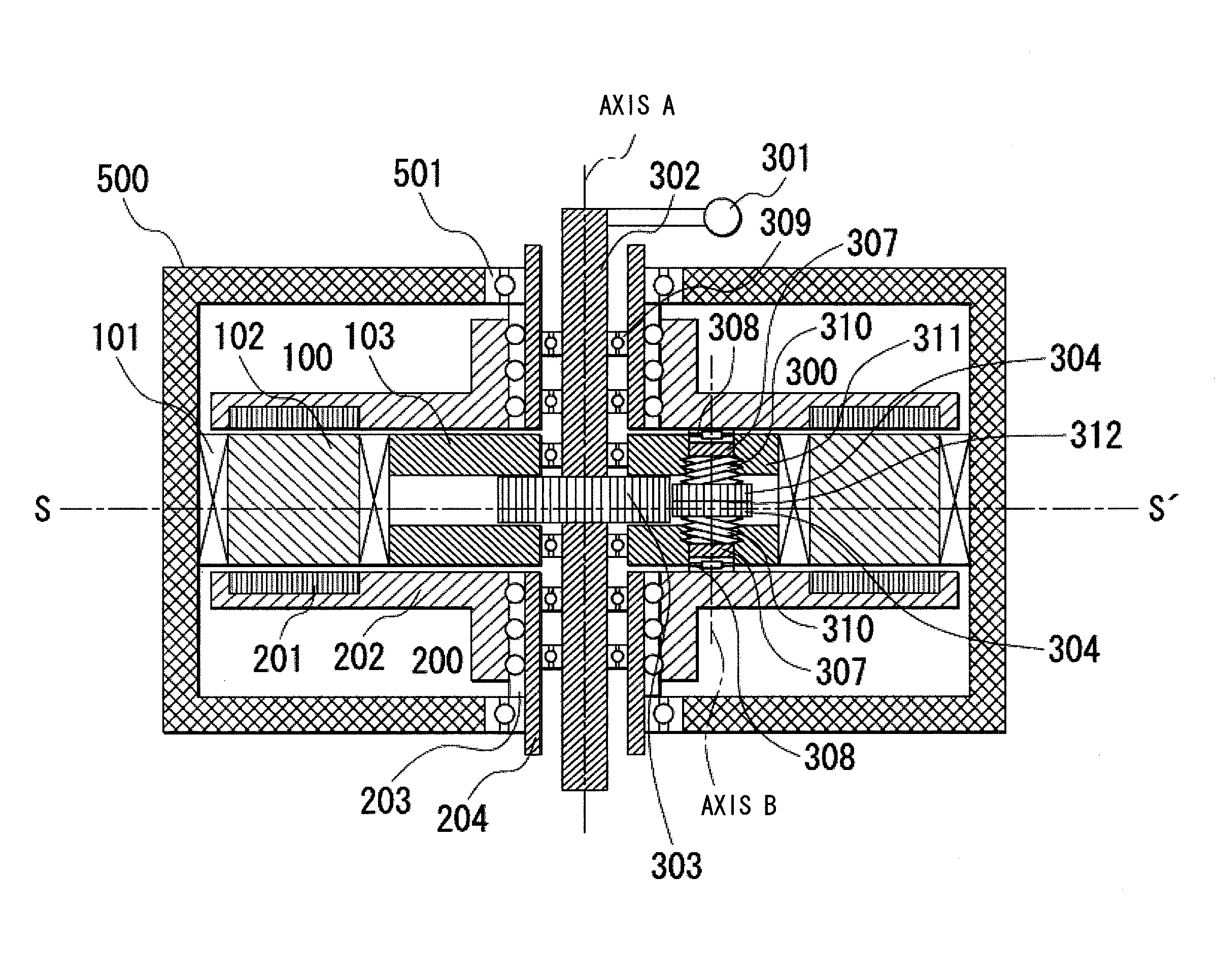
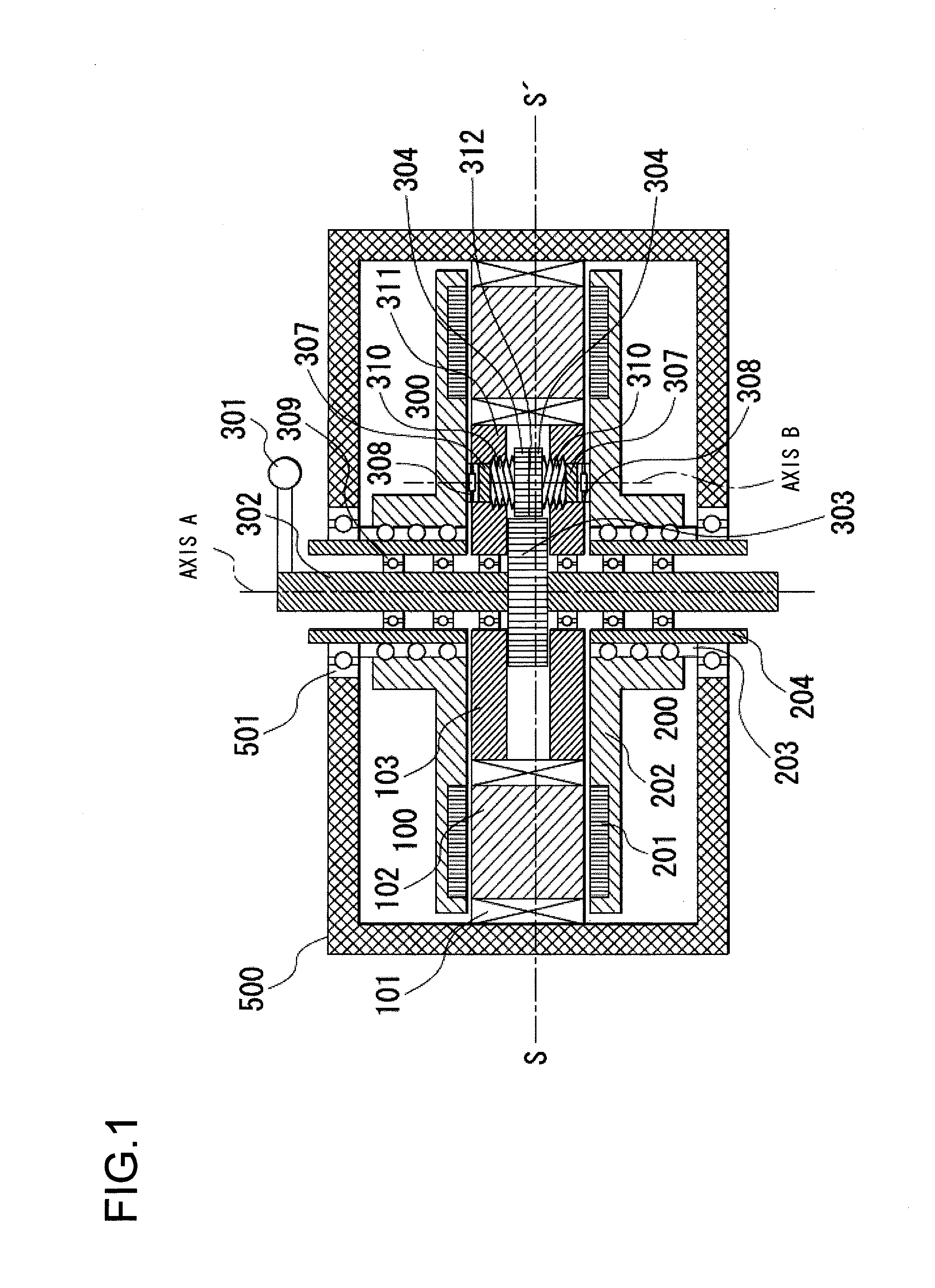
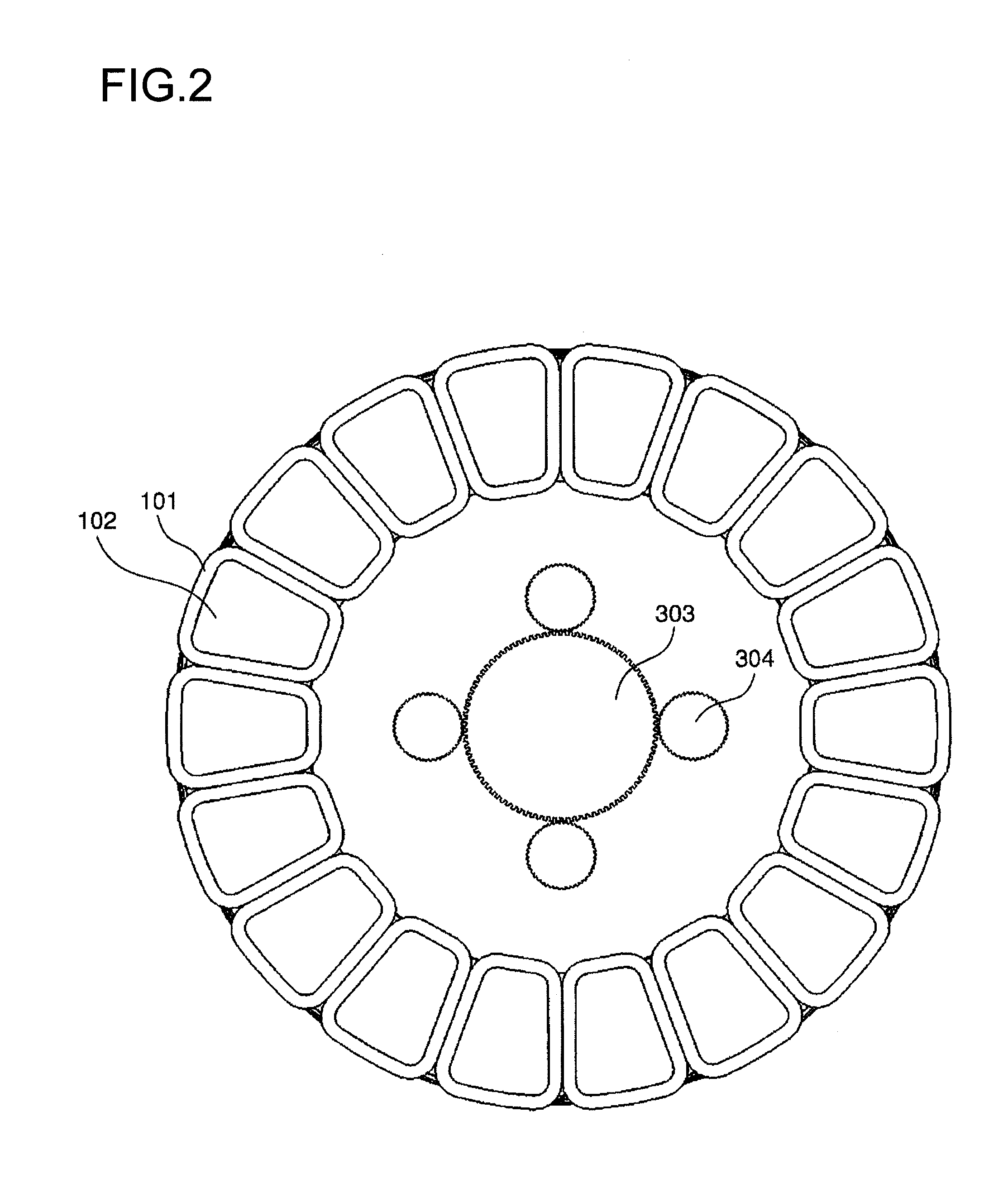
[0044]FIGS. 1 through 4 and 5A and 5B show the first embodiment of the axial gap type rotating electrical machine according to the present invention. FIGS. 1, 5A, and 5B are axial sectional views as seen from the radial direction, FIG. 2 is a diametrical sectional view as seen from the axial direction, FIG. 3 is a perspective view of FIG. 2, and FIG. 4 is a sectional view of the perspective view of FIG. 3. Here, the radial direction is a direction orthogonal to the rotational axis of the rotor, and the axial direction is the direction along the rotational axis of the rotor.

[0045]The rotating electrical machine, which means here an axial flux permanent magnet brushless machine or an axial gap type rotating electrical machine, according to the present invention includes a stator 100, two rotors 200, a variable gap mechanism 300, and a housing 500.

[0046]The stator 100 includes a plurality of coils 101 that are arranged in its circumferential direction around an axis A as a center and a...

Example

[0055]FIG. 6 is a figure showing the second embodiment of the axial gap type rotating electrical machine according to the present invention. In this embodiment, the upper and lower output shafts 204 of the axial gap type rotating machine shown in the first embodiment are connected via torque transmission mechanisms 402 to a single external output shaft 401 that rotates around an axis C exterior to the housing. The torque transmission mechanisms 402 may, for example, be bevel gears or belts or the like.

[0056]In this second embodiment, the output torques of the output shafts 204 that rotate around the axis A are transmitted via the torque transmission mechanisms 402 to the external output shaft 401 that rotates around the axis C.

[0057]By transmitting the output torques of the upper and lower output shafts 204 to a single shaft in this manner, it becomes possible to ensure that the rotation of the shafts 204 and also their torques agree with one another, even though the output shafts 2...

Example

[0058]FIG. 7 is a figure showing the third embodiment of the axial gap type rotating electrical machine according to the present invention. It should be understood that, in FIG. 7, the housing 500 and the bearings 501 are omitted.

[0059]This embodiment is one in which the relative position in the rotational direction of the upper and lower rotors 200 of the axial gap type rotating electrical machine described in the first embodiment is fixed (while they are free to move relative to one another in the axial direction). This rotating electrical machine according to the third embodiment is provided with a rotor coupling mechanism 403 between the upper and lower rotors 200 for performing this relative rotational fixing. The rotor coupling mechanism 403 is a system for mechanically coupling the relative position of the upper and lower rotors 200 in the rotational direction, and may be, for example, a cylinder or the like. Moreover, one or more rotor coupling mechanisms 403 of this type ar...


PUM


Abstract

An axial flux permanent magnet brushless machine according to the present invention includes: a housing; a stator comprising a stator core and a coil; two rotors each including a permanent magnet, and positioned so as to sandwich the stator in the axial direction with air gaps being left between the rotors and the stator; and a variable gap mechanism for changing distances of the air gaps; wherein the variable gap mechanism operates from a power source that supplies other rotational power than a rotational power of the axial flux permanent magnet brushless machine, and changes the distances of the air gaps by shifting the rotors in the axial direction.

Description

INCORPORATION BY REFERENCE[0001]The disclosure of the following priority application is herein incorporated by reference: Japanese Patent Application No. 2010-276517, filed Dec. 13, 2010.BACKGROUND OF THE INVENTION[0002]1. Field of the Invention[0003]The present invention relates to an axial flux permanent magnet brushless machine, in which a stator and a rotor oppose one another in the axial direction with an air gap being defined between them.[0004]2. Description of the Related Art[0005]In a rotating electrical machine in which a permanent magnet is provided to a rotor, an induced voltage is generated during rotation. It is necessary for the power supply voltage for such a rotating electrical machine (i.e. the inverter output voltage) to be greater than or equal to this induced voltage, since the induced voltage increases in proportion to the rotational speed.[0006]In order to suppress increase of the induced voltage with an axial flux permanent magnet brushless machine, which is ...

Claims


Application Information

Patent Timeline
IPC IPC(8): H02K21/24
CPCH02K21/026
Inventor TOKOI, HIROOKIENOMOTO, YUJI
Owner HITACHI LTD
Why Eureka
Try Eureka