LED lighting module and lighting device using the module

a technology of led lighting and modules, which is applied in outdoor lighting, semiconductor devices for light sources, lighting and heating apparatus, etc., can solve the problems of reducing limiting the improvement of heat radiating characteristics, and increasing manufacturing costs, so as to prevent shortening the lifespan of led packages and enhancing heat radiating characteristics

Inactive Publication Date: 2012-06-14
GIGATERA INC
View PDF20 Cites 3 Cited by
  • Summary
  • Abstract
  • Description
  • Claims
  • Application Information

AI Technical Summary

Benefits of technology

[0015]Accordingly, the present invention has been made to solve the above-mentioned problems occurring in the prior art, and the present invention provides an LED light-emitting module which prevents shortening of the lifespan of LED packages by enhancing heat radiating characteristics, and an illumination apparatus using the same.

Problems solved by technology

In particular, while it is required to enhance the heat radiating characteristics of an LED street lamp employing a plurality of LED packages, there is a limit in enhancing smooth heat radiating characteristics with a structure in which heat radiating fins are provided on the rear surface of a printed circuit board (PCB) having a plurality of LED packages.
In spite of many efforts to enhance heat radiating characteristics by increasing the number and height of heat radiating fins, there is also a limit in improving heat radiating characteristics as air cannot be convected in spaces between the heat radiating fins.
However, as it is relatively difficult to manufacture heat radiating fins of different heights, and there is a need to process groove patterns for easy flow of air in a central upper side of the heat radiating fins, manufacturing costs increase and productivity decreases.
Moreover, in the conventional technology, while a housing protrudes from a side of the LED mounting surface contacting a board to which LED chips are mounted, toward a lower side and some of the heat radiating fins are placed outside the protruding portion, the heat radiating fins on the side have an area remarkably small as compared with the area of the heat radiating fins placed on the rear side of the LED mounting surface, resulting in a very small amount of radiated heat.
This is because, considering that heat radiating efficiency is basically proportional to the area of the heat radiating fins to a certain degree, heat radiating effect is low and heat is radiated mainly to the rear side of the LED mounting surface, resulting in lowering of heat radiating efficiency.
In addition, in the conventional technology, there exist portions of a frame except for an area of the heat radiating fins whose thicknesses are partially different from the other portions, in which case the lifespan of some of the LED chips becomes shortened due to partial non-uniformity of temperatures caused by differences between the thicknesses of the frame, resulting in a shortened lifespan of the entire LED light-emitting apparatus.
Meanwhile, as an LED package has a narrow light radiating angle as compared with a general light source of a different type lamp, a more complex mechanical structure is needed to comply with a minimal light radiation angle range of a street lamp which is also related to the height of the street lamp.
However, it is not easy to design such a structure and without increasing manufacturing costs.
Although the conventional technology can satisfy the illumination intensity issue when a plurality of illumination apparatuses are disposed in parallel, they respectively include a rotor for rotation, making their mechanisms for individually driving the rotors very complex and making it difficult to configure the mechanisms.
Further, the outwardly protruding rotors contact a coupling plate, making it difficult to adjust their angles.

Method used


Image

  • LED lighting module and lighting device using the module
  • LED lighting module and lighting device using the module
  • LED lighting module and lighting device using the module

Examples


Embodiment Construction

[0034]Hereinafter, LED light-emitting modules and illumination apparatuses according to embodiments of the present invention will be described in detail with reference to the accompanying drawings.

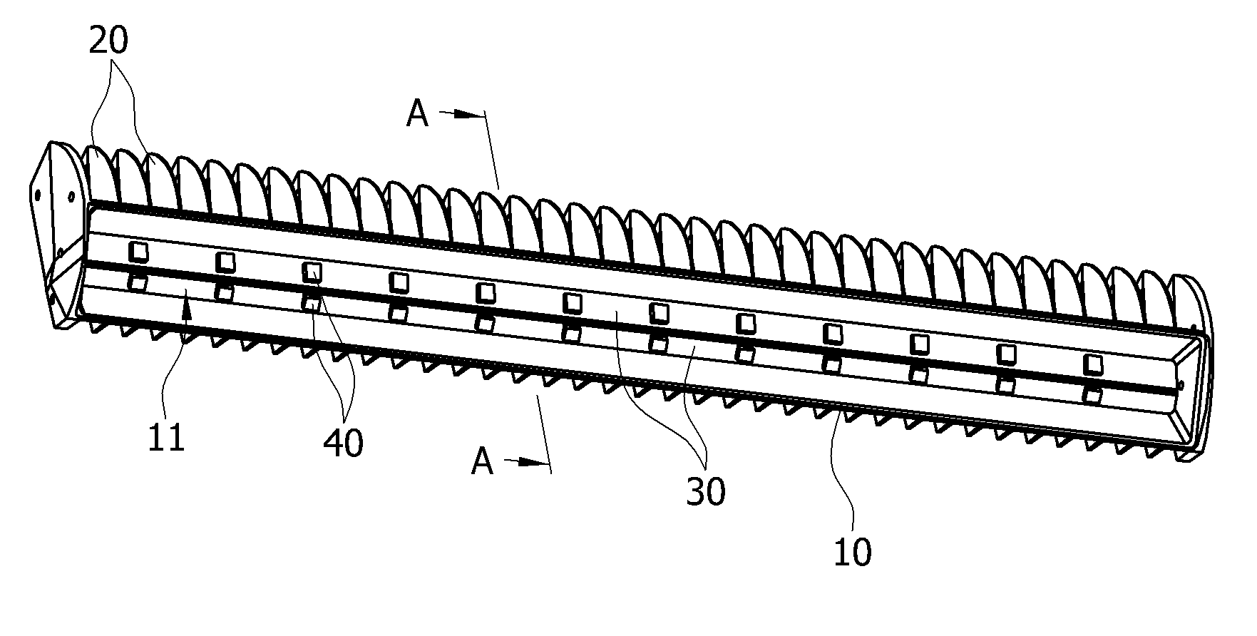
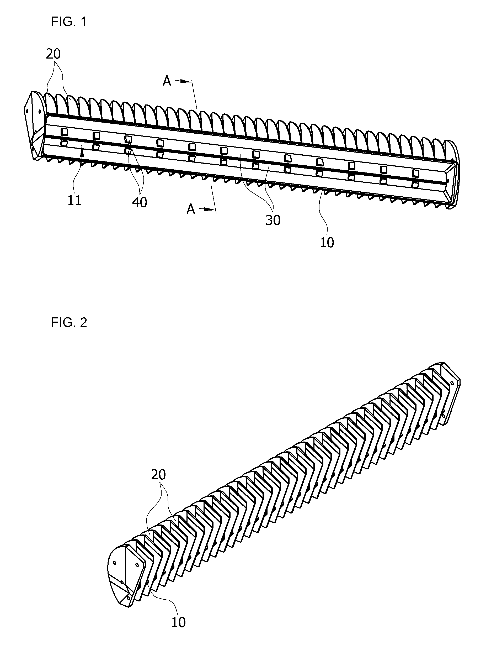
[0035]FIG. 1 is a bottom perspective view of an LED light-emitting module according to an embodiment of the present invention. FIG. 2 is a top perspective view of FIG. 1. FIG. 3 is a sectional view taken along line A-A of FIG. 1.

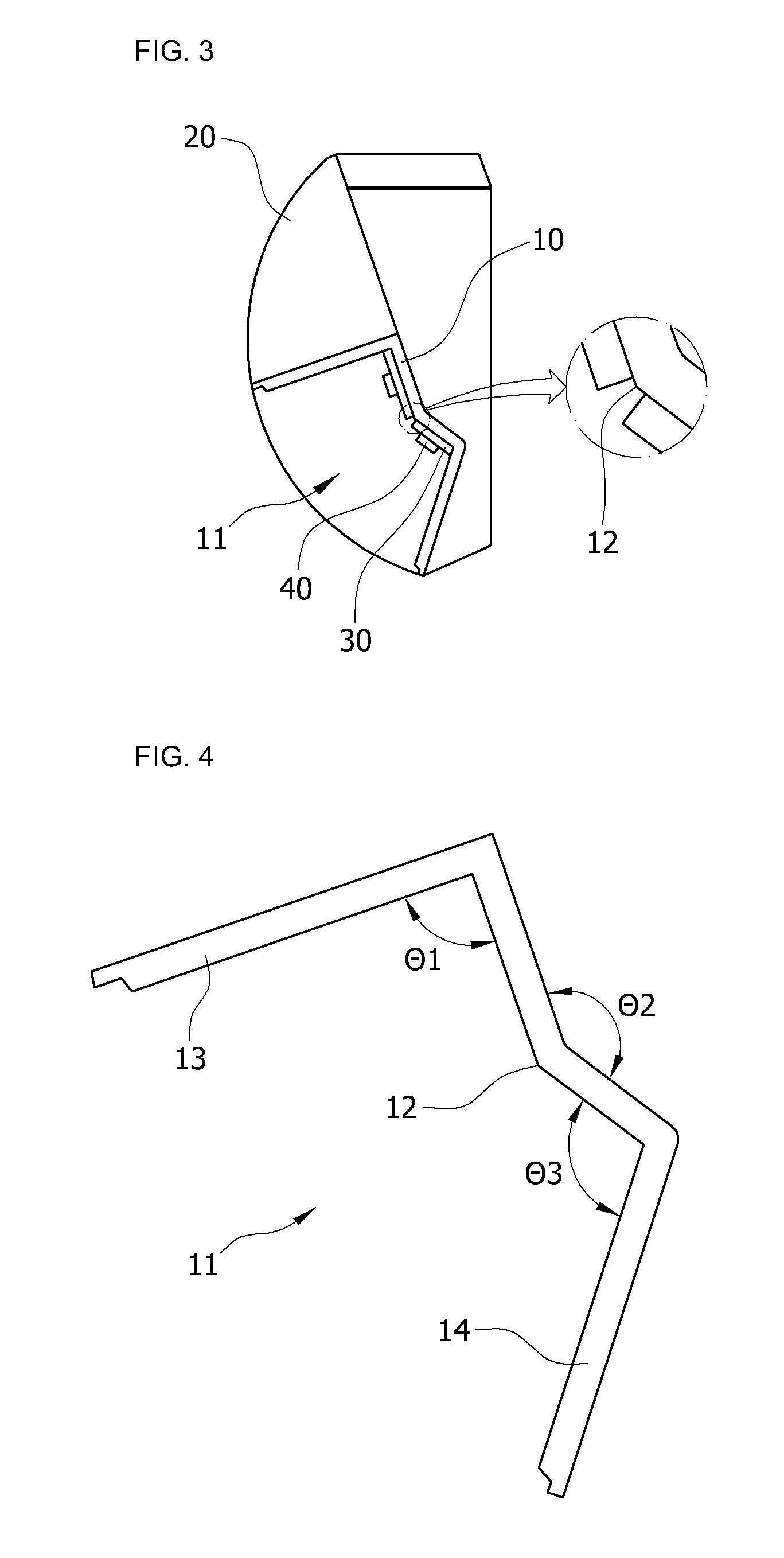
[0036]Referring to FIGS. 1 to 3, an LED light-emitting module according to the embodiment of the present invention includes a body frame 10 having a light emitting opening 11 in a direction inclined with respect to a ground surface by a certain angle and a bent coupling surface 12, a plurality of semi-circular heat radiating fins 20 placed on the entire surface of the body frame 10 except for the heat emitting opening 11 so as to be spaced apart from each other, and metal PCBs 30 coupled to the coupling surface 12 of the body frame 10, and a plurality of LED packag...


PUM


Abstract

Provided are an LED light-emitting module and an illumination apparatus using the same. The LED light-emitting module includes a body frame having a light emitting opening in a direction inclined with respect to a ground surface and a coupling surface to which an LED package is coupled, the body frame including reflective plates extending from opposite sides of the coupling surface to define the light emitting opening, a plurality of heat radiating fins placed on the entire surface of the body frame except for the light emitting opening, and a plurality of LED packages installed on the coupling surface of the body frame such that light radiation angles of the LED packages are adjusted according to an angle by which the coupling surface is bent.

Description

BACKGROUND OF THE INVENTION[0001]1. Field of the Invention[0002]The present invention relates to an LED light-emitting module and an illumination apparatus using the same, and more particularly, to an LED light-emitting module with excellent heat radiating characteristics whose light radiation angle can be easily adjusted, and an illumination apparatus using the same.[0003]2. Description of the Related Art[0004]In recent years, LEDs are being studied as an illumination unit due to their low power consumption and long lifespan as compared with general light sources. As heat generated in LED packages shortens the lifespan, structures for smoothly radiating the heat of the LED packages are also being widely studied and developed.[0005]In particular, while it is required to enhance the heat radiating characteristics of an LED street lamp employing a plurality of LED packages, there is a limit in enhancing smooth heat radiating characteristics with a structure in which heat radiating fin...

Claims


Application Information

Patent Timeline
Patent Type & Authority Applications(United States)
IPC IPC(8): H01J13/32F21V5/00F21V7/00
CPCF21V7/0025F21V29/004F21Y2101/02F21V29/763F21Y2111/004F21W2131/103F21V29/2212F21V7/005F21K9/27F21Y2103/10F21Y2115/10F21Y2107/20F21V29/70F21V29/76
Inventor KIM, DUK-YONG
Owner GIGATERA INC
Why Eureka
Try Eureka