In-folding convertible roof

a convertible roof and convertible technology, applied in the field of convertible roofs, can solve the problems of presenting the difficulty of packaging (stowing), and increasing the difficulty of packaging, so as to increase the size of the passenger compartment and/or the size, minimize the packaging space, and maximize the available space

Inactive Publication Date: 2007-07-24
SPECIALTY VEHICLE ACQUISITION
View PDF62 Cites 18 Cited by
  • Summary
  • Abstract
  • Description
  • Claims
  • Application Information

AI Technical Summary

Benefits of technology

[0004]Most traditional convertible roofs are stowed in a bootwell or stowage compartment that is located aft of a passenger compartment in the vehicle. A boot or tonneau cover is then used to cover the bootwell and conceal the convertible roof from view and / or protect the stowed roof from the environment. Optionally, a portion of the convertible roof can be visible when in the stowed position and provide a desired appearance for the vehicle.
[0006]The available space for the stowage compartment in a vehicle, however, may be at a premium. That is, while it is desirable to provide a vehicle with a convertible roof, it is also desirable to provide sufficient storage space in the vehicle for use in storing objects other than the convertible roof. Thus, it would be advantageous to minimize the packaging space required to stow the convertible roof while maximizing the available space for other purposes, such as maintaining or increasing the size of the passenger compartment and / or the size of the general storage area or trunk of the vehicle when produced with a convertible roof.
[0007]Moreover, when the convertible roof spans a large passenger seating area the controlling of the final movements of the convertible roof when being raised or retracted may cause significant stress or torque to be exhibited on the components of the convertible roof. This increased force may be undesirable and may cause a reduction in the lifespan of the components that comprise and drive the convertible roof. Thus, it would be advantageous to minimize the impact or force imparted on the driving components of the convertible roof when reaching the fully extended or fully retracted state.
[0008]In accordance with the present invention, a convertible roof is provided which includes a segmented pair of front roof rails that in-fold when being retracted. The in-folding advantageously reduces the packaging space required to stow the convertible roof. In another aspect of the present invention, in-folding of the segmented front roof rails is controlled by synchronizing linkages between the segmented portions and the number one roof bow which synchronize the in-folding of the segmented front roof rails. The synchronization advantageously eliminates side-to-side drift of the convertible roof when moving between the raised and stowed positions. In accordance with another aspect of the present invention, a damper is employed to dampen a portion of the motion of the convertible roof as the top reaches a fully extended and fully retracted position. The dampening advantageously reduces high forces or stresses that are imparted on the drive mechanisms during the movement of the convertible roof between the extended and retracted positions.

Problems solved by technology

Traditional soft-top convertible roofs, such as those discussed above, can present a packaging (stowing) difficulty when it is desired to use a “Z” folding roof.
The difficulty is more pronounced when a “Z” folding roof is desired to be used on a larger vehicle (vehicle having front and rear seating areas).
Additionally, the use of three pairs of coupled roof rails also adds to the packaging difficulty.
Moreover, when the convertible roof spans a large passenger seating area the controlling of the final movements of the convertible roof when being raised or retracted may cause significant stress or torque to be exhibited on the components of the convertible roof.
This increased force may be undesirable and may cause a reduction in the lifespan of the components that comprise and drive the convertible roof.

Method used


Image

  • In-folding convertible roof
  • In-folding convertible roof
  • In-folding convertible roof

Examples


Embodiment Construction

[0023]The following description of the preferred embodiment is merely exemplary in nature and is in no way intended to limit the invention, its application, or uses. As used herein, the term “substantially perpendicular” allows for some limited deviation from 90°, such as 90°±5°.

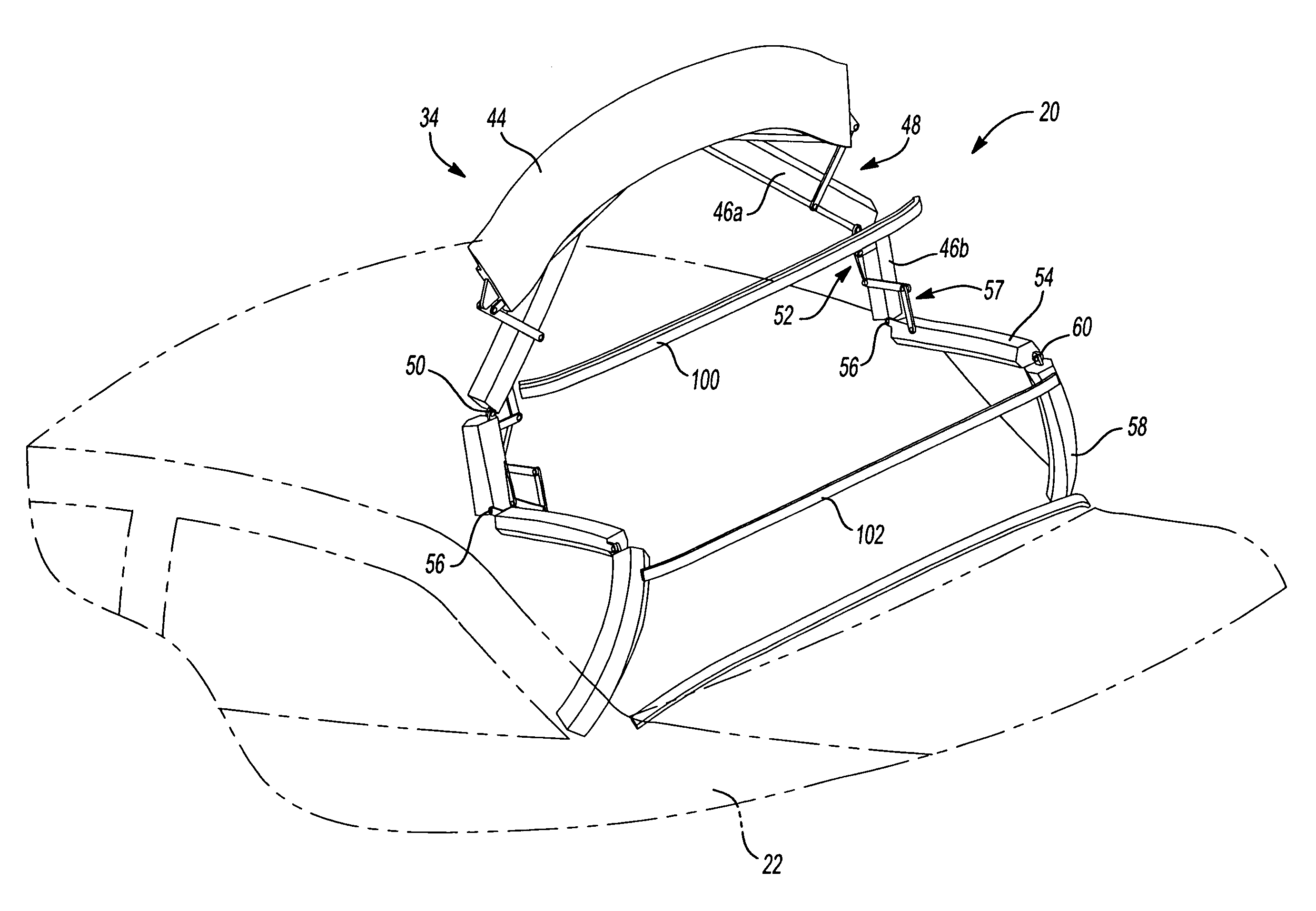
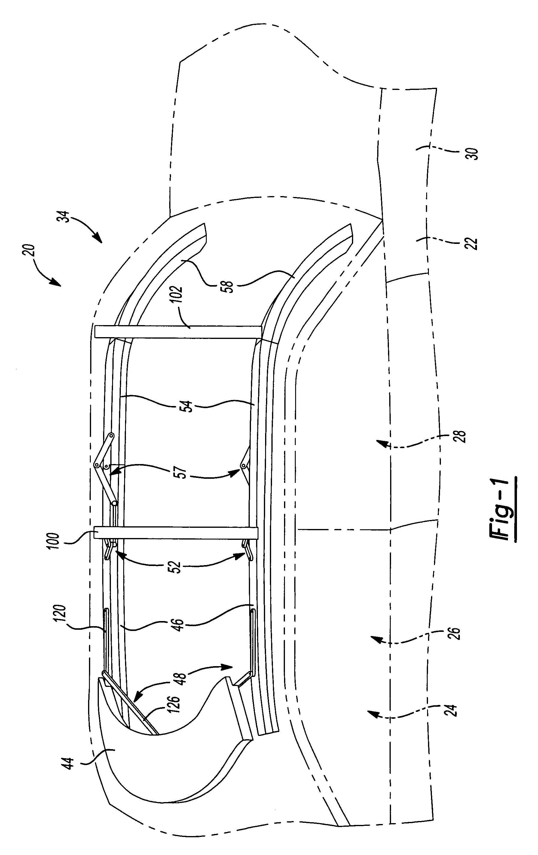
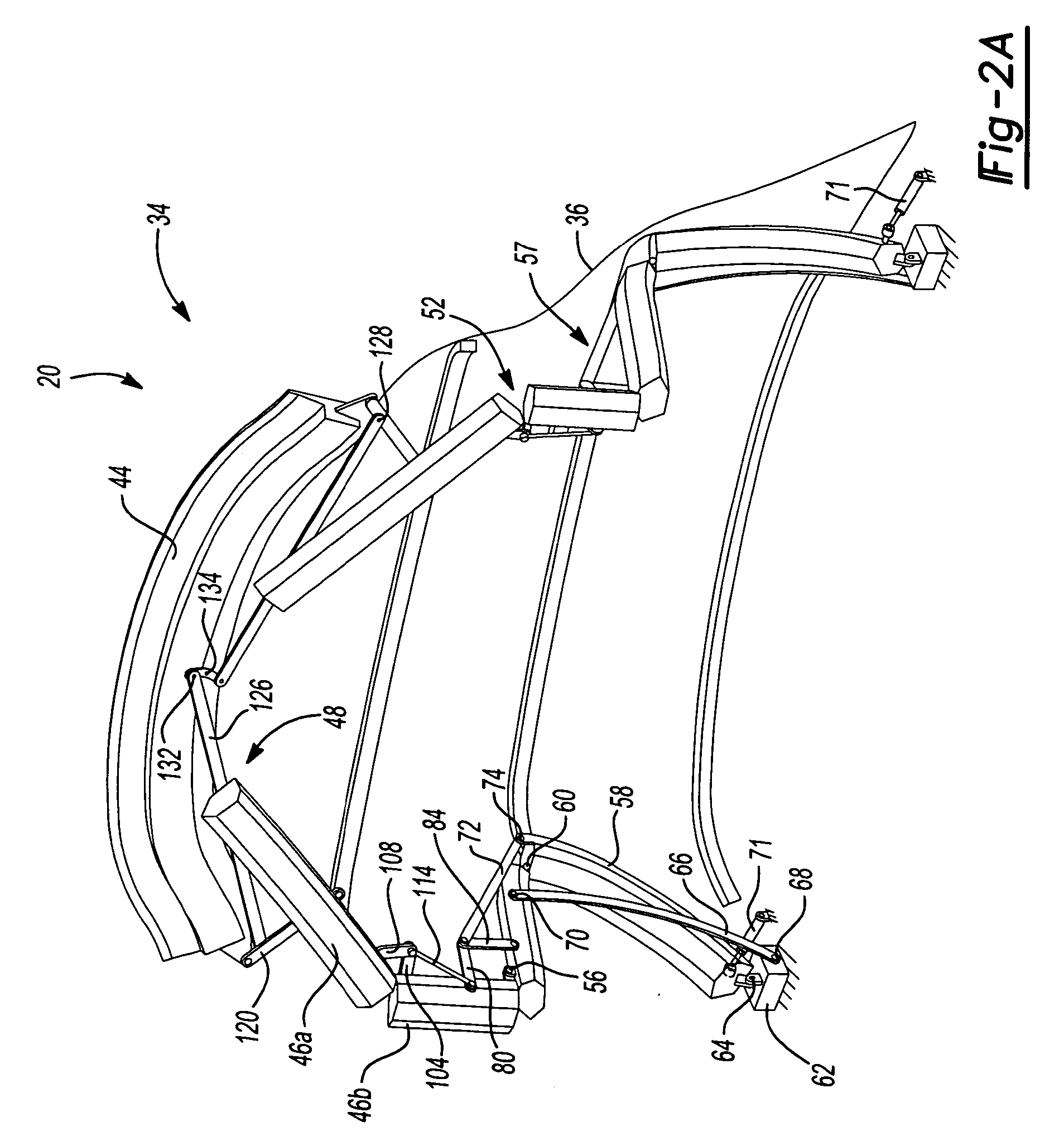
[0024]FIGS. 1-5 show an alternate embodiment of an in-folding convertible roof 20 according to the principles of the present invention. Convertible roof 20 is employed on an automotive vehicle 22 having a passenger compartment 24 with front and rear passenger seating areas 26, 28 and a generally U-shaped bootwell or stowage compartment 30. Stowage compartment 30 is positioned aft of passenger compartment 24 with quarter trim portions extending along a portion of sides of passenger compartment 24. Convertible roof 20 is of the type utilizing a folding or top stack mechanism 34 and a roof cover 36 (shown in FIG. 2A only) and is operable between a fully raised position, as shown in FIG. 1, through intermediate ...


PUM


Abstract

A convertible roof includes a segmented pair of front roof rails that in-fold when being retracted, thereby reducing the packaging space required to stow the convertible roof. The in-folding of the segmented front roof rails is controlled by linkages between the segmented portions and the number one roof bow and synchronizes and constrains the in-folding of the segmented front roof rails. A dampening device is utilized to dampen a portion of the movement of the top stack mechanism between extended and retracted positions.

Description

CROSS-REFERENCE TO RELATED APPLICATION[0001]This application claims the benefit of U.S. Provisional Application Ser. No. 60 / 612,384, filed on Sep. 23, 2004. The disclosure of the above application is incorporated herein by reference.BACKGROUND AND SUMMARY OF THE INVENTION[0002]The present invention relates to convertible roofs and, more particularly, to in-folding convertible roofs.[0003]Traditional soft-top convertible roofs for automotive vehicles typically employ three, four or five roof bows, having an inverted U-shape spanning transversely across the vehicle for supporting a vinyl, canvass or polyester fabric pliable roof cover. A number one roof bow is mounted to a pair of front roof rails and is typically latched to a stationary front header panel of the automotive vehicle body disposed above the front windshield. A number two roof bow is typically mounted to either the front roof rails or to a pair of center roof rails which are pivotally connected to the front roof rails. F...

Claims


Application Information

Patent Timeline
Patent Type & Authority Patents(United States)
IPC IPC(8): B60J7/12
CPCB60J7/0069
Inventor DILLUVIO, CHRISTOPHER J.
Owner SPECIALTY VEHICLE ACQUISITION
Why Eureka
Try Eureka