Digging tooth mounting assembly and digging tooth

a technology for mounting assemblies and digging teeth, which is applied in the direction of soil-shifting machines/dredgers, constructions, etc., can solve the problems of large amount of stress generated, tooth tends to pivot even more, wear of the surfaces in contact between the adapter and the digging tooth, etc., to suppress wear, control the pivoting, and suppress the effect of wear

Active Publication Date: 2015-01-15
KOMATSU LTD
View PDF25 Cites 16 Cited by
  • Summary
  • Abstract
  • Description
  • Claims
  • Application Information

AI Technical Summary

Benefits of technology

[0023]In the digging tooth according to the eighth exemplary embodiment of the present invention, dirt and the like entering between the contact surfaces of the digging tooth and the adapter travel into the recess, thus suppressing wear.
[0024]The present invention provides a digging tooth mounting assembly and digging tooth whereby it is possible to control pivoting and suppress wear.

Problems solved by technology

External forces acting on the digging tooth lead to (i) a large amount of stress being generated between the adapter and the digging tooth, (ii) the digging tooth pivoting slightly relative to the adapter, and (iii) dirt and the like entering between the contact surfaces of the adapter and the digging tooth, resulting in wear of the surfaces in contact between the adapter and the digging tooth.
The tooth tends to pivot even more when the contact surfaces of the adapter and tooth wear.
Once the amount of pivoting increases, the contact surface wears even further, creating a detrimental cycle that precipitates wear.
Consequently, this shortens the lifespan of the components.

Method used


Image

  • Digging tooth mounting assembly and digging tooth
  • Digging tooth mounting assembly and digging tooth
  • Digging tooth mounting assembly and digging tooth

Examples


Embodiment Construction

[0035]Exemplary embodiments of the present invention will be described with reference to the drawings. In the following exemplary embodiments, an excavator bucket 100 used on a work machine, such as a hydraulic excavator and the like, will be described as one example of an excavating tool.

[0036]Overall Configuration of the Bucket 100

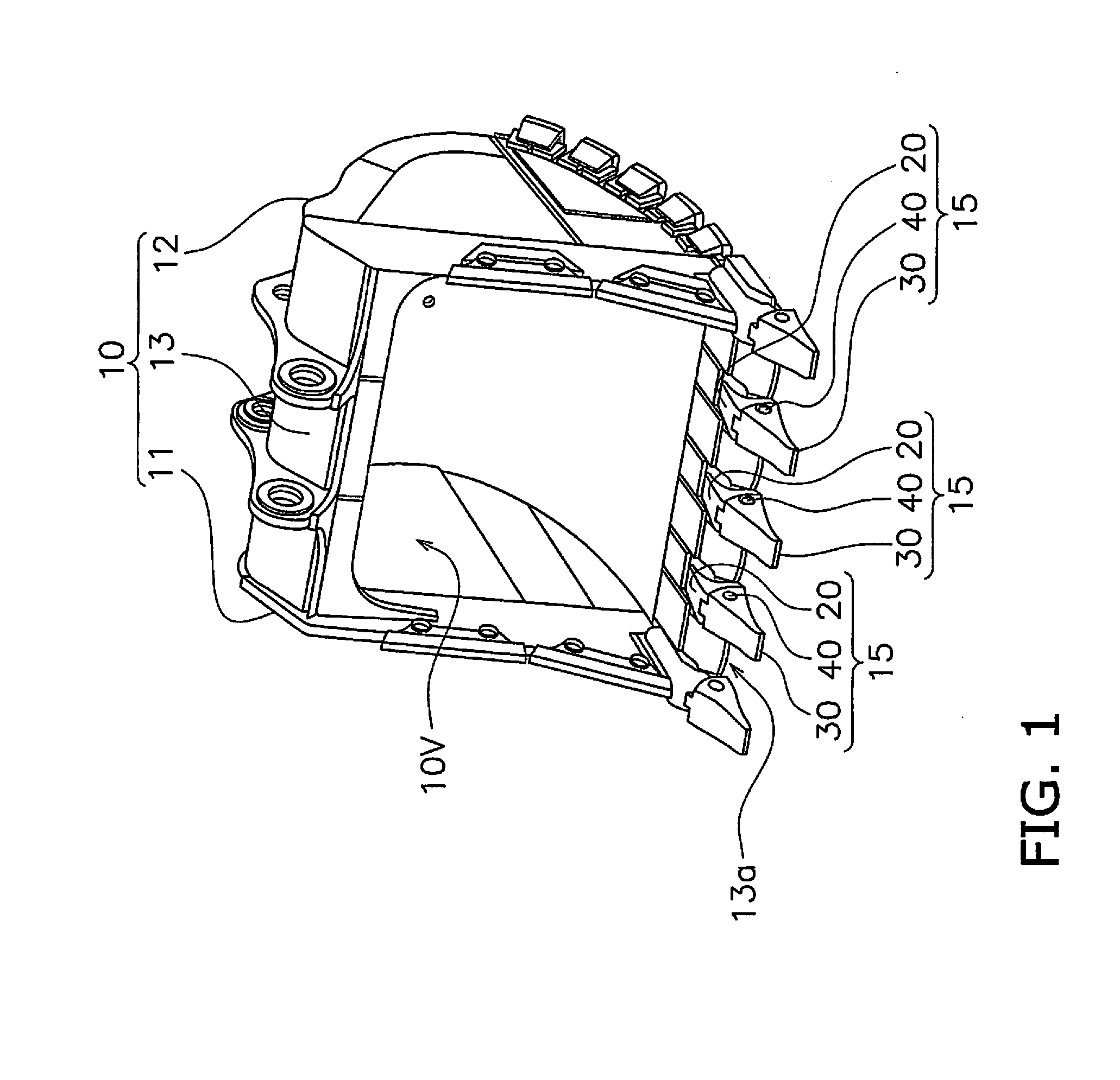
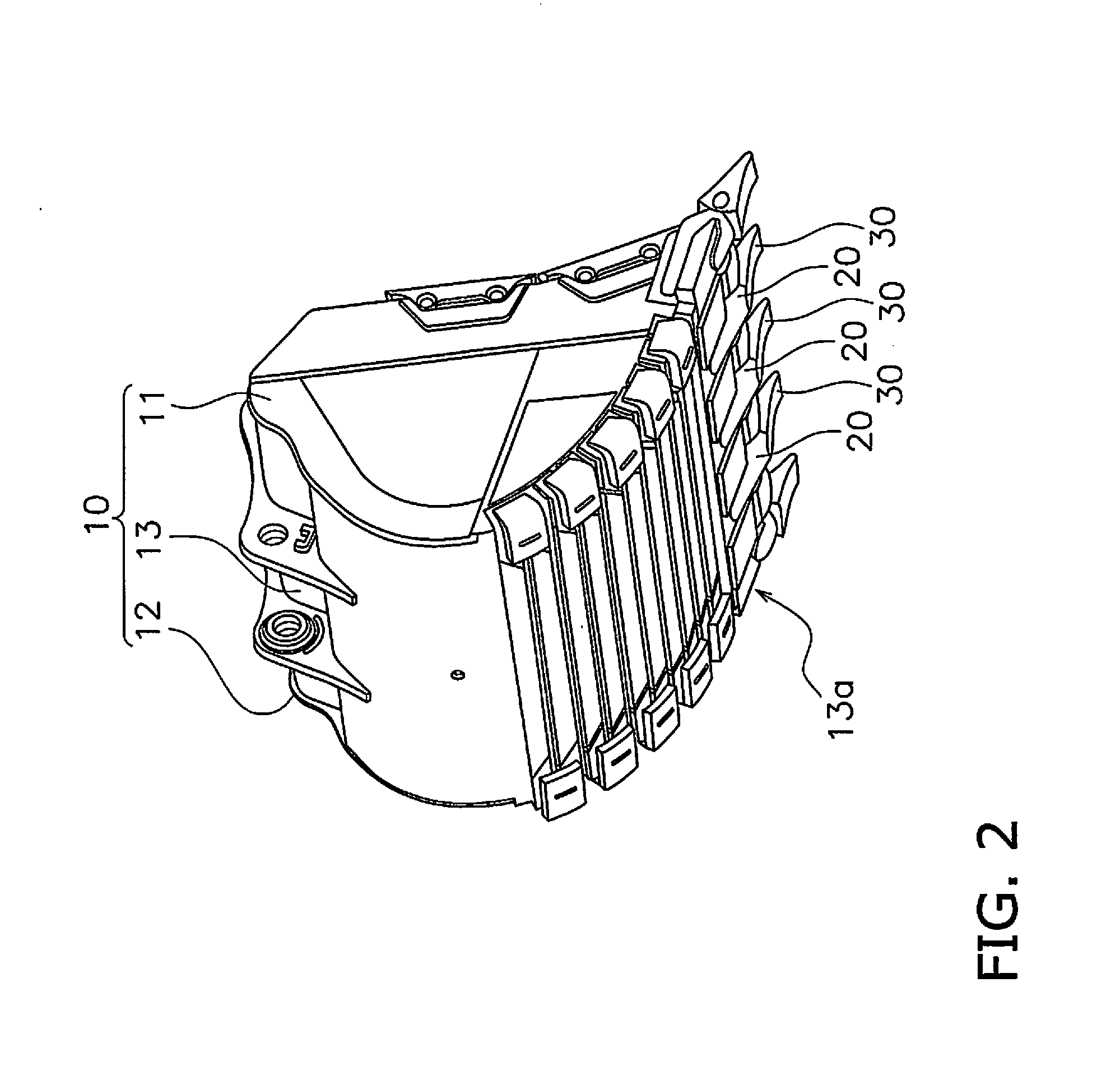
[0037]FIGS. 1 and 2 are perspective views of the bucket 100. As illustrated in FIGS. 1 and 2, the bucket 100 is provided with a bucket body 10, and a plurality of digging tooth mounting assemblies 15.

[0038]The bucket body 10 includes a first sidewall 11, a second sidewall, and a wrapper 13. The first sidewall 11 and the second sidewall 12 face each other. The first sidewall 11 and the second sidewall 12 are each flat sheets, and in side view, are each shaped as a flat sheet surrounded by a substantially circular arc and a bow string. The wrapper 13 is a curved sheet arranged along the substantially circular arc of the first sidewall 11 and the second sid...


PUM


Abstract

A digging tooth mounting assembly has an adapter, a digging tooth and a retainer assembly. The adapter includes a front surface facing the digging tooth, a recess formed on the front surface, an inserted part projecting from the front surface, and a insertion through hole formed in the inserted part for receiving the retainer assembly. The digging tooth includes a rear surface facing the front surface of the adapter, a projecting part formed on the rear surface for insertion into the recess, an insertion hole formed on the rear surface for receiving the inserted part, and a pair of shaft bores for receiving the retainer assembly. An outer peripheral surface of the projecting part is spaced apart from an inner bottom surface and an inner side surface of the recess.

Description

CROSS-REFERENCE TO RELATED APPLICATIONS[0001]This application is a U.S. National stage application of International Application No. PCT / JP2013 / 083691, filed on Dec. 17, 2013. This U.S. National stage application claims priority under 35 U.S.C. §119(a) to Japanese Patent Application No. 2012-275320, filed in Japan on Dec. 18, 2012, the entire contents of which are hereby incorporated herein by reference.BACKGROUND[0002]1. Field of the Invention[0003]The present invention relates to a digging tooth mounting assembly and a digging tooth used on a work machine.[0004]2. Background Information[0005]Work vehicles, such as a hydraulic excavator and the like, are generally provided with an excavating tool, such as a bucket or ripper. An adapter with a projection segment is secured, for instance, at the tip end of the bucket. A tooth, which is a cutting edge, includes an insertion hole that receives the projection segment of the adapter so that the digging tooth can be installed on the adapte...

Claims


Application Information

Patent Timeline
Patent Type & Authority Applications(United States)
IPC IPC(8): E02F9/28
CPCE02F9/2833E02F9/2808E02F9/2825E02F9/2858
Inventor TANAKA, KENICHIAIRA, TATSUO
Owner KOMATSU LTD
Why Eureka
Try Eureka