Transformer incorporated in electronic circuits

a transformer and electronic circuit technology, applied in the direction of transformer/react mounting/support/suspension, basic electric elements, electrical apparatus, etc., can solve the problems of difficult to completely prevent the vibration of the transformer, and generate noise, so as to effectively suppress prevent and suppress the effect of the vibration of the transformer

Active Publication Date: 2012-06-14
NIPPON SOKEN +1
View PDF7 Cites 8 Cited by
  • Summary
  • Abstract
  • Description
  • Claims
  • Application Information

AI Technical Summary

Benefits of technology

[0015]In the configuration mentioned above, the transformer has the first gaps in which the respective spacers are provided. Thus, when magnetic attractive force is caused between the upper core and the lower core, each spacer is able to prevent the upper core and the lower core from displacing in the direction along which the upper and lower cores come close to each other. As a result, vibration of the upper cores and the lower core is suppressed to thereby suppress the vibration noise of the transformer.
[0037]Further, it is preferable that a vibration absorber is interposed between the lower core and the base plate. In this case, the vibration absorber absorbs the vibration of the lower core to suppress the vibration of the lower core. Also, being interposed between the lower core and the base plate, the vibration absorber is able to suppress the vibration of the transformer from being transmitted to the base plate. As a result, in a vehicle, for example, installing the transformer, the vibration noise is effectively suppressed from being transmitted to the vehicle cabin.

Problems solved by technology

In other words, the vibration of the cores 3 and 2 is transmitted to the vehicle cabin, for example, of the vehicle that installs the DC-DC converter, and generates noise.
Specifically, in spite of providing the spacer or the pressing member, it is sometimes difficult to completely prevent the vibration of the transformer.

Method used


Image

  • Transformer incorporated in electronic circuits
  • Transformer incorporated in electronic circuits
  • Transformer incorporated in electronic circuits

Examples


first embodiment

[0056]With reference to the accompanying drawings, hereinafter are described several embodiments of a transformer according the present invention.

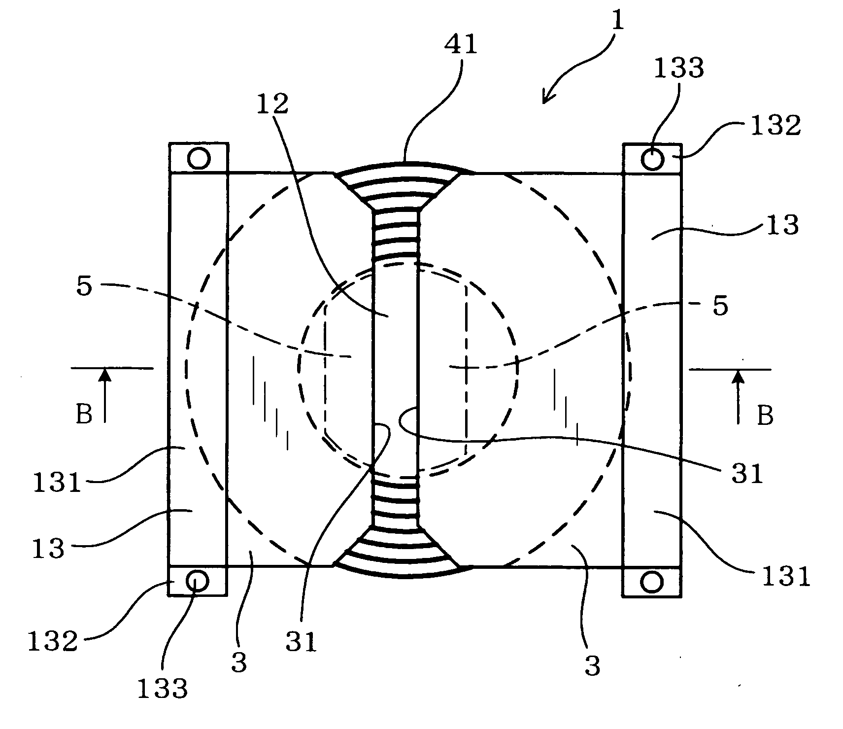
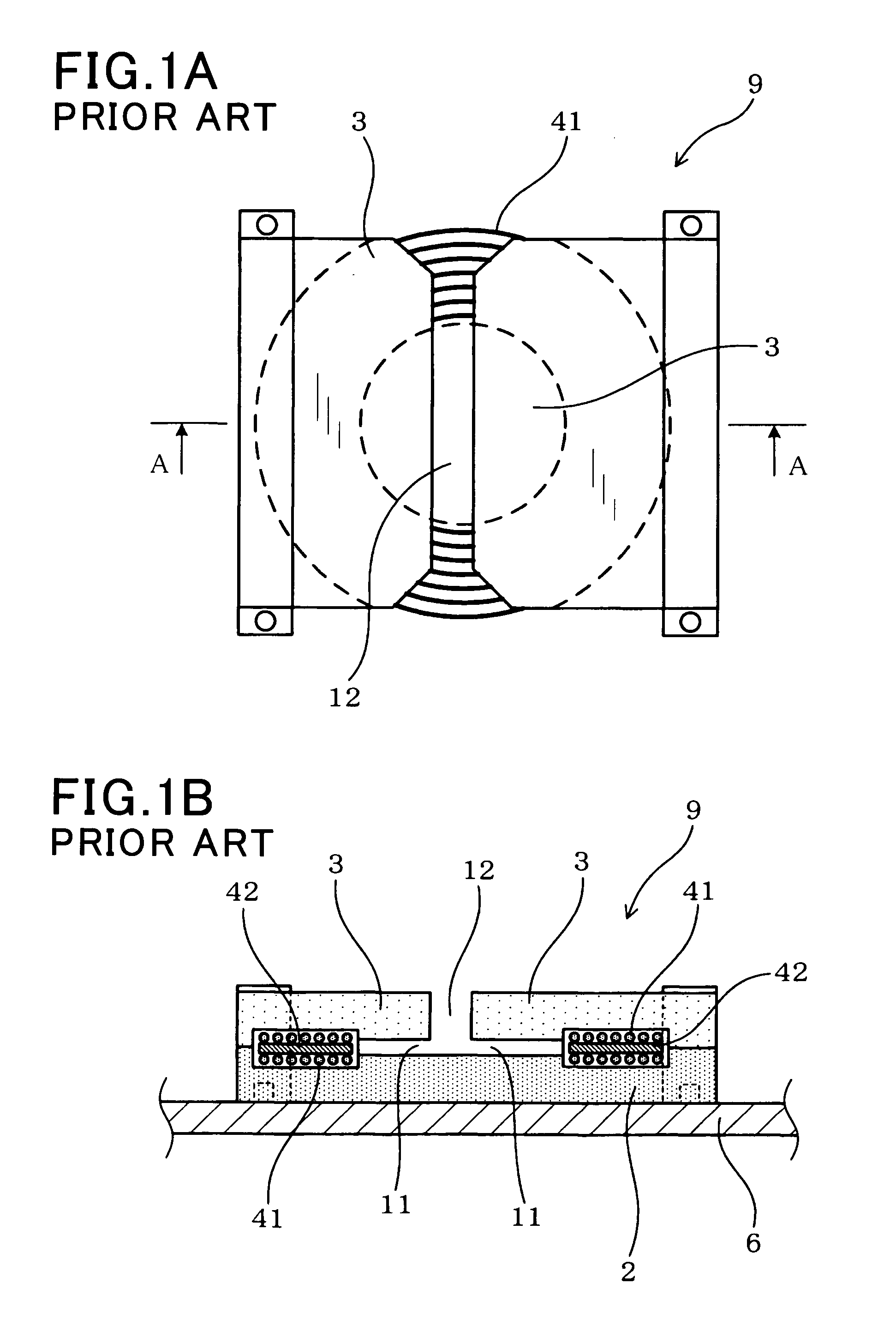
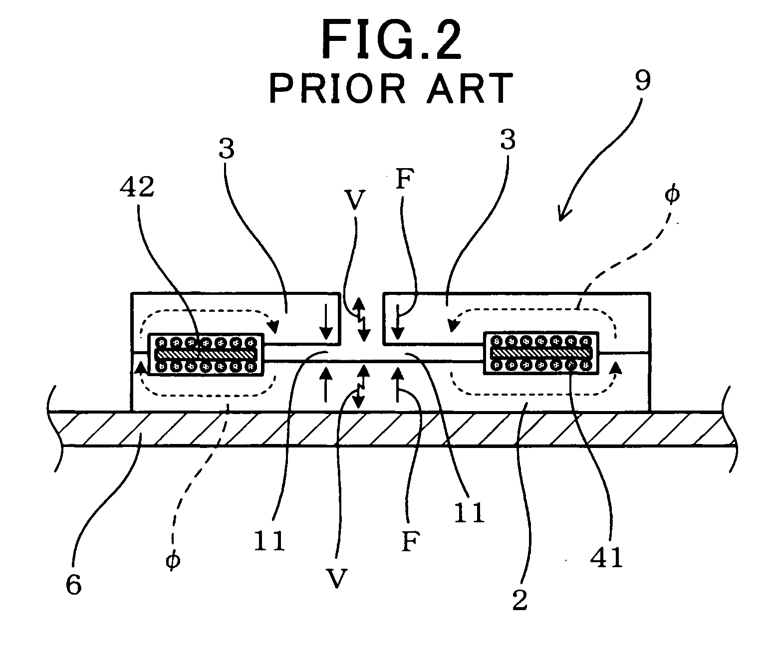
[0057]Referring, first, to FIGS. 3A and 3B, a transformer according to a first embodiment is described. FIG. 3A is a plan view illustrating a transformer 1 according to the first embodiment. FIG. 3B is a cross-sectional view taken along a line B-B of FIG. 3A. It should be appreciated that, throughout the embodiments, the components identical with or similar to those of the transformer based on conventional art mentioned above and shown in FIGS. 1A, 1B and 2 are given the same reference numerals for the sake of omitting unnecessary explanation.

[0058]As shown in FIGS. 3A and 3B, the transformer 1 includes a lower core 2, two upper cores 3, primary coils 41 and a secondary coil 42. The lower core 2 made of a magnetic material has an upper surface and a lower surface and is arranged on the base plate 6 through the lower surface. The two upper ...

second embodiment

[0074]Referring to FIGS. 4A and 4B, a second embodiment of the present invention is described. FIG. 4A is a plan view illustrating a transformer 1 according to the second embodiment. FIG. 4B is a cross-sectional view taken along a line C-C of FIG. 4A.

[0075]As shown in FIGS. 4A and 4B, the transformer 1 of the second embodiment includes a spacer 5 which is extended not only into the first gaps 11 but also into the second gap 12.

[0076]Specifically, in the second embodiment, the spacer 5 has a base portion 51 and a projected portion 52 which is projected upward from substantially the center of the base portion 51. The base portion 51 surrounding the projected portion 52 is located in the first gaps 11, while the projected portion 52 is located in the second gap 12.

[0077]The base portion 51 is formed into a disc-like shape, while the projected portion 52 is formed into a columnar shape. The base portion 51 has a lower surface contacting the upper surface of the lower core 2, and has an ...

third embodiment

[0081]Referring to FIGS. 5A and 5B, a third embodiment of the present invention is described. FIG. 5A is a plan view illustrating a transformer 1 of the third embodiment. FIG. 5A is a cross-sectional view taken along a line D-D of FIG. 5A.

[0082]As shown in FIGS. 5A and 5B, the transformer 1 of the third embodiment includes a lower core 2 having a non-contact surface 21 in the lower surface thereof. The non-contact surface 21 is not in contact with the base plate 6.

[0083]The non-contact surface 21 has an area that occupies not less than a half of the area of the lower surface of the lower core 2.

[0084]Specifically, the lower surface of the lower core 2 is provided with legs 22 at the respective four corners. Being provided with the legs 22, the lower surface of the lower core 2 is provided with the non-contact surface 21 not contacting the base plate 6. Also, being provided with the legs 22, a space is formed between the non-contact surface 21 of the lower core 2 and the upper surfac...


PUM

PropertyMeasurementUnit
frequencyaaaaaaaaaa
drive frequencyaaaaaaaaaa

Abstract

A vibration-suppressed transformer is fixed to a base plate and includes a magnetic lower core, two or more magnetic upper cores, primary and secondary coils. The lower core is on the base plate. The upper cores are arranged face to face over the lower core. The coils are arranged between the lower and upper cores. Each upper core contacts the lower core, on an outer side of the coils, with a first gap being provided between the upper and lower cores, on an inner side of the coils. The upper cores are extended towards each other from the outer to the inner side of the coils, with a second gap being provided therebetween. The second gap is provided therein with a non-magnetic pressing member to press the lower core against the base plate, on an inner side of the coils.

Description

CROSS-REFERENCE TO RELATED APPLICATION[0001]This application is based on and claims the benefit of priority from earlier Japanese Patent Application No. 2010-277986 filed Dec. 14, 2010, the description of which is incorporated herein by reference.BACKGROUND[0002]1. Technical Field[0003]The disclosure relates to a transformer incorporated in electronic circuits such as DC-DC converters.[0004]2. Related Art[0005]Some DC-DC converters use transformers to perform voltage conversion of DC power. One of such DC-DC converters is shown in FIGS. 1A, 1B and 2. FIG. 1A is a plan view illustrating a transformer based on conventional art. FIG. 1B is a cross-sectional view taken along a line A-A of FIG. 1A. FIG. 2 is an explanatory view illustrating vibration of the transformer based on conventional art.[0006]As shown in FIG. 1B, a transformer 9 is fixed to a base plate 6 that is a metal plate made of aluminum or the like. The transformer 9 includes a lower core 2, at least two upper cores 3, pri...

Claims


Application Information

Patent Timeline
Patent Type & Authority Applications(United States)
IPC IPC(8): H01F27/24
CPCH01F27/06H01F27/28H01F27/266
Inventor GOTO, TOMOYUKIYASUDA, MASANORIMATSUOKA, HISANAGATAKEMOTO, YUUKI
Owner NIPPON SOKEN
Why Eureka
Try Eureka