Physiological data acquisition utilizing vibrational identification

a technology of vibration identification and data acquisition, applied in the field of physiological measurement techniques and biotelemetry, can solve the problems of ct scanners suffering from numerous disadvantages, ekg does not produce an image of the heart itself, and is not a direct measurement of motion,

Inactive Publication Date: 2012-06-14
MATHAI TOM +1
View PDF6 Cites 87 Cited by
  • Summary
  • Abstract
  • Description
  • Claims
  • Application Information

AI Technical Summary

Problems solved by technology

The electrodes must be physically connected to the patient being monitored, which can be bothersome to the patient, for the duration of the EKG test.
In addition, an EKG does not produce an image of the heart itself and is not a direct measurement of the motion of the heart.
Yet, CT scanners suffer from numerous disadvantages.
They are expensive, bulky and immobile, require patients to remain generally immobile for extended periods of time during the scanning, and expose patients to potentially harmful x-rays.
As with CT scanners, MRI scanners are expensive, very large and immobile, and require patients to remain relatively immobile during the procedure.
Furthermore, MRI scanners cannot be used by some people with metal implants.

Method used


Image

  • Physiological data acquisition utilizing vibrational identification
  • Physiological data acquisition utilizing vibrational identification
  • Physiological data acquisition utilizing vibrational identification

Examples


Embodiment Construction

[0021]Further features and advantages of the invention, as well as the structure and operation of various embodiments of the invention, are described in detail below with reference to the accompanying FIGS. 1-5, wherein like reference numerals refer to like elements.

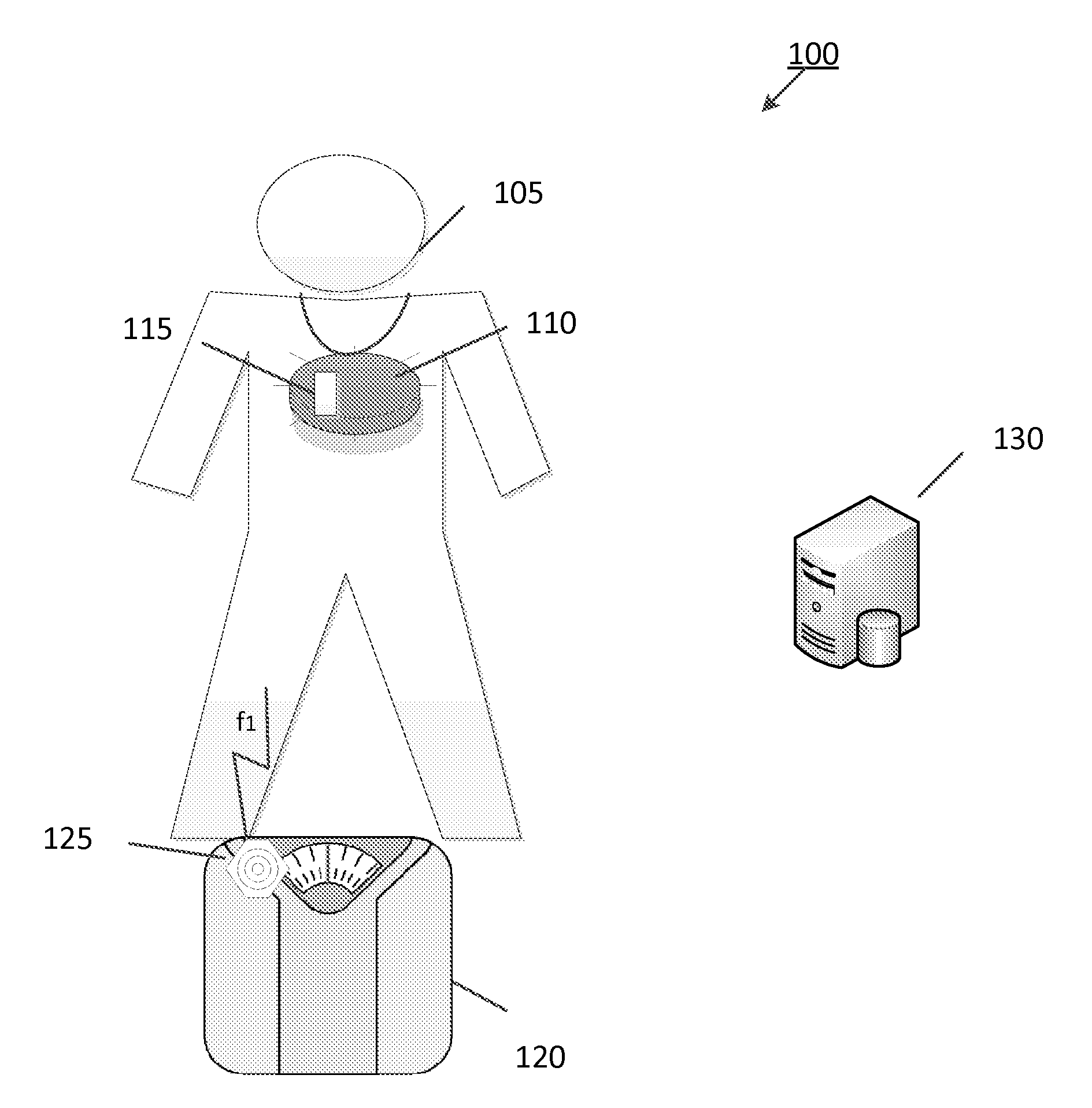
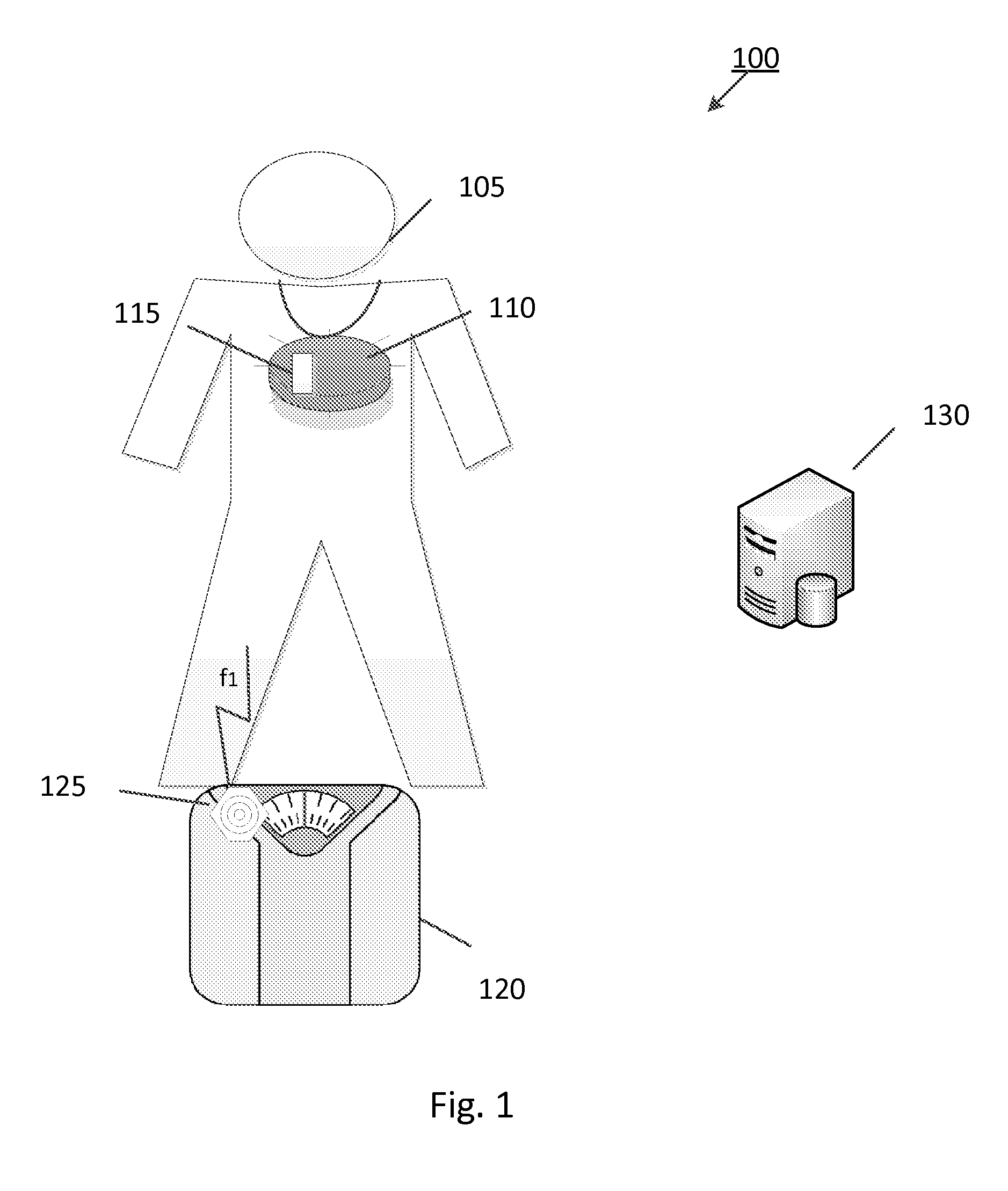
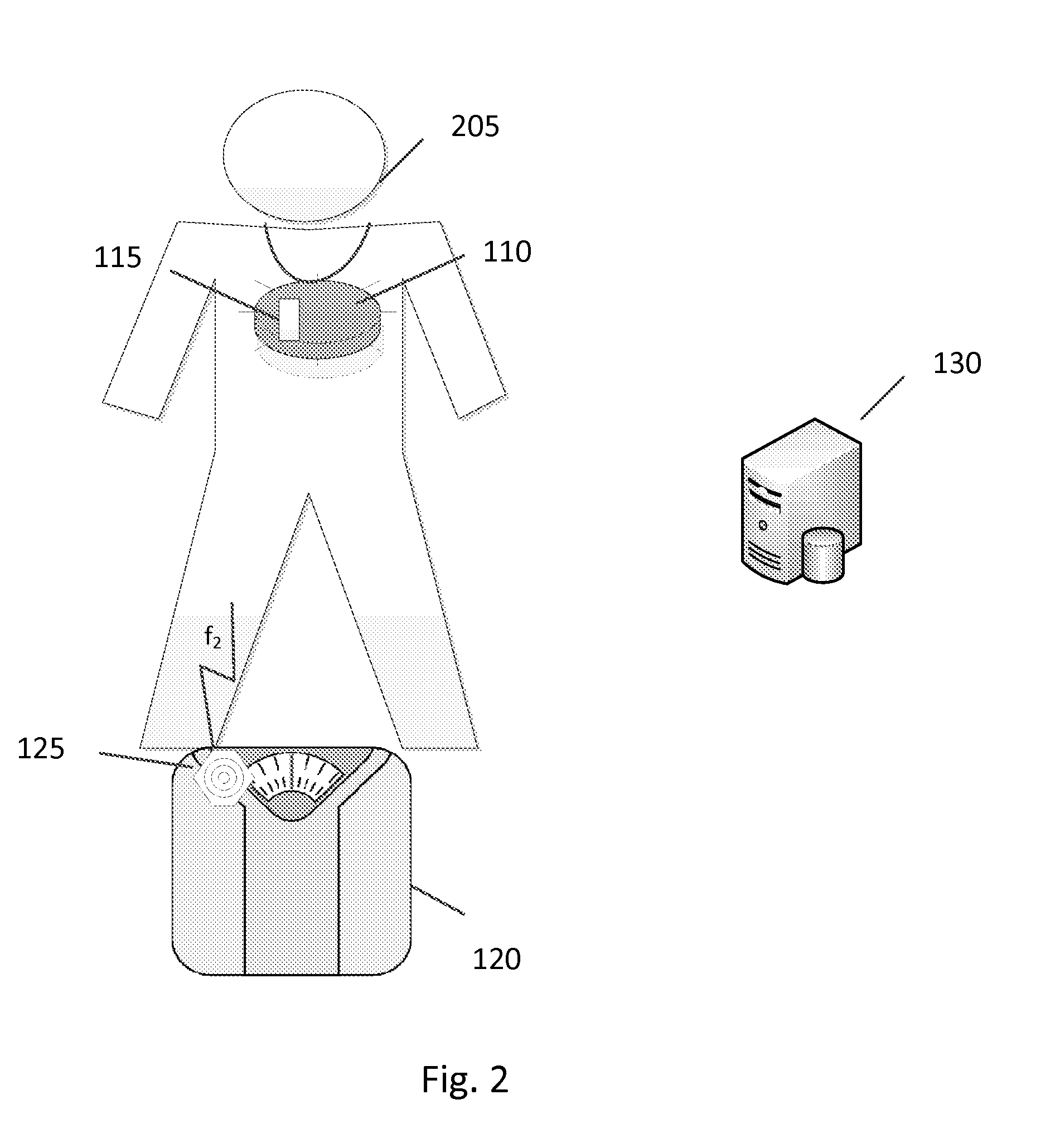
[0022]U.S. patent application Ser. No. 12 / 712,488, entitled “Wireless Physiology Monitor,” the entire disclosure of which is incorporated by reference herein, describes a new non-invasive technique for physiology monitoring and assessment implemented by, for example, a wireless physiology monitoring device. Particularly, a patient is subjected to a non-harmful and relatively low power electromagnetic RF source diagnostic signal normally associated with a communications protocol such as, but not limited to a version of the IEEE 802.11(x) family of protocols in the 2.4, 3.6, or 5 GHz spectrum bands. The source diagnostic signal could be generated by the wireless physiology monitoring device itself or taken from background ...


PUM


Abstract

The present invention utilizes an accelerometer (included within a wireless physiology monitoring device or as part of a separate device such as, but not limited to a smartphone, e.g., iPhone, or other mobile device) to link a patient with a separate medical data acquisition device such as a weight scale or a blood pressure monitor in order to collect and transmit a range of medical data associated with the user. The medical data acquisition device includes a vibration source for emitting a vibration at a predetermined or random frequency. When the acquisition device is activated, a vibration is transmitted from the through the patient and is detected by the accelerometer. The accelerometer then measures the particular frequency of vibration and transmits this information to a centralized monitoring unit (CMU). Based on the measured frequency, the CMU is able to know that the same patient wearing / holding the device is also the same patient using the data acquisition device. The vibration source may revolve through a number of predetermined frequencies (as determined on its own or instructed via the CMU) or simply generate a random frequency.

Description

CROSS-REFERENCE TO RELATED APPLICATIONS[0001]This continuation-in-part application claims the benefit of U.S. patent application Ser. No. 12 / 712,488 and PCT / US10 / 253,325, both filed on Feb. 25, 2010, and both entitled “WIRELESS PHYSIOLOGY MONITOR,” which claim priority under 35 U.S.C. §119(e) to U.S. Provisional Patent Application No. 61 / 155,510, entitled “WiFi OFDM Modulated Carrier for Heart and Lung Monitoring,” filed Feb. 25, 2009, and U.S. Provisional Patent Application No. 61 / 179,605, entitled “Fall Detection and Heart / Lung Monitoring,” filed May 19, 2009. The entireties of such applications are incorporated herein by reference.BACKGROUND OF THE INVENTION[0002]1. Field of Invention[0003]The present invention relates to physiological measurement techniques and biotelemetry (i.e., medical telemetry), and more particularly to a system, device, and method for linking patient or device identifiers with medical test data through vibrational frequency magnitudes.[0004]2. Description ...

Claims


Application Information

Patent Timeline
Patent Type & Authority Applications(United States)
IPC IPC(8): G08B23/00G16H40/67
CPCA61B5/002G06F19/3418A61B5/021A61B5/0402A61B5/05A61B5/082A61B5/11A61B5/1117A61B5/117A61B5/14532A61B5/14546A61B5/14551A61B2562/0219G06F19/322G06F19/3406A61B5/0028G16H40/63G16H10/60G16H40/67A61B5/318
Inventor MARGON, KENNETHRENUKANAND, GUBBI UMESH
Owner MATHAI TOM
Why Eureka
Try Eureka