Antenna characterization in a waveguide

a waveguide and antenna technology, applied in the direction of antennas, instruments, antenna radiation diagrams, etc., can solve the problems of relatively expensive, relatively time-consuming and/or costly measurement, and limited effective bandwidth,

Active Publication Date: 2012-06-14
ROSENBERGER HOCHFREQUENZTECHNIK GMBH & CO KG
View PDF0 Cites 131 Cited by
  • Summary
  • Abstract
  • Description
  • Claims
  • Application Information

AI Technical Summary

Benefits of technology

[0007]Bearing in mind the problems and deficiencies of the prior art, it is therefore an object of the present invention to pr

Problems solved by technology

A disadvantage of this method is that measuring is relatively time-consuming and/or costly, since several reference antennas often need to be provided and measured in succession, as such reference antennas display a limited, relatively narrow effective bandwidth.
In order also to provide a high purity of polarization, precisely manufactured and absolutely characterized reference a

Method used


Image

  • Antenna characterization in a waveguide
  • Antenna characterization in a waveguide
  • Antenna characterization in a waveguide

Examples


Embodiment Construction

)

[0030]In describing the preferred embodiment of the present invention, reference will be made herein to FIGS. 1-11 of the drawings in which like numerals refer to like features of the invention.

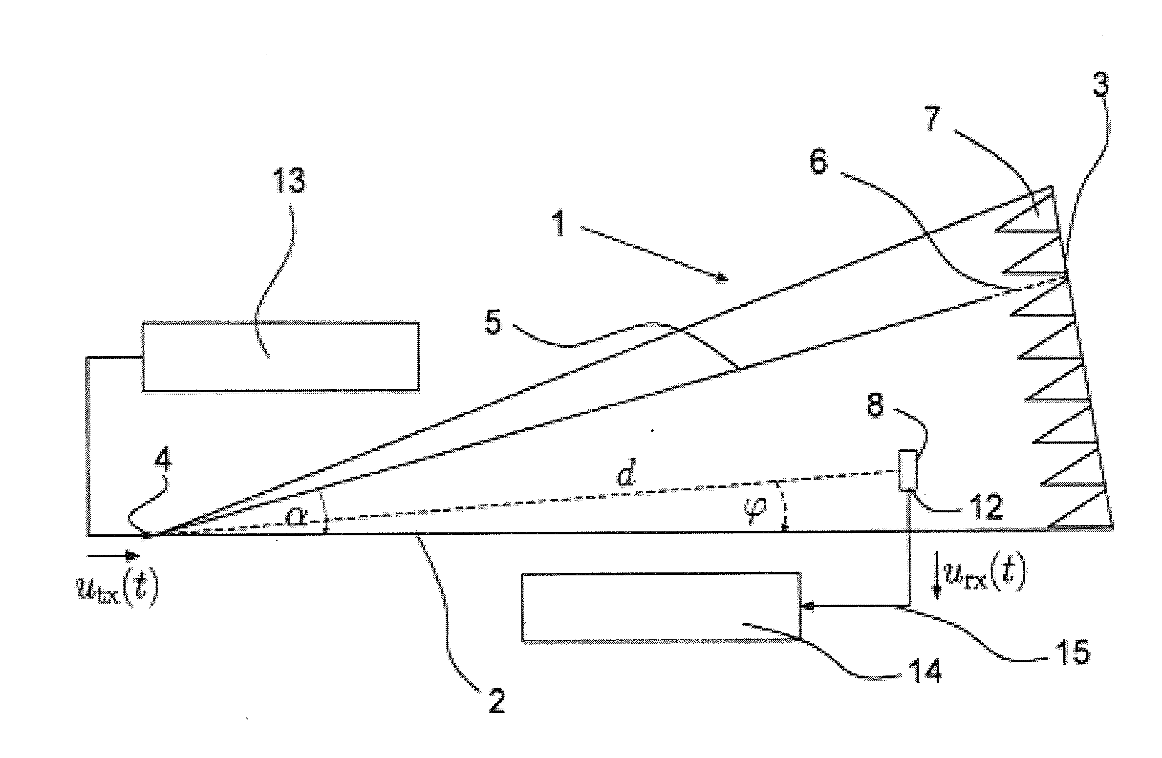
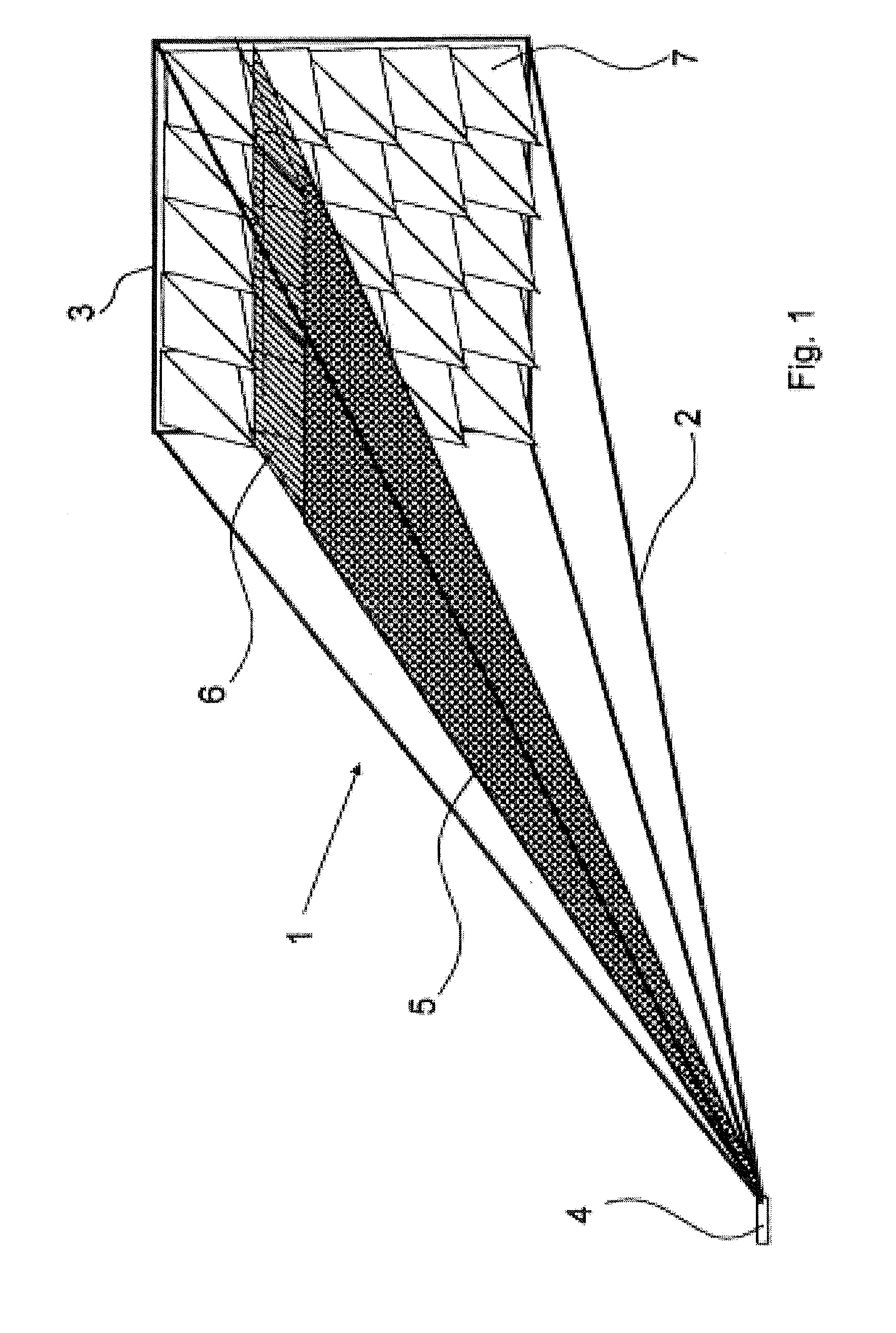
[0031]The invention can, advantageously, be realized using simple means. It is advantageous that use can be made of widely-used measuring devices, for example a waveguide. Fundamentally, all types of waveguide which offer sufficient space for the placement of the antenna and which, at least at times, provide a TEM field at the location of the antenna can be considered as suitable for application of the invention. A TEM field is the term used to describe a transverse electromagnetic field in which the field vector of the electric field and the field vector of the magnetic field are perpendicular to one another and both field vectors are perpendicular to the direction of propagation.

[0032]Accordingly, various arrangements can be considered as waveguides which can be used advantageously in perf...


PUM


Abstract

A method for determining at least one characteristic of an antenna requiring: a) positioning an antenna in a space surrounded by a waveguide; b) feeding an electric excitation signal (utx(t)) into a feed connection of the waveguide; c) receiving the electric response signal (urx(t)) emitted by the antenna resulting from the excitation signal (utx(t)); d) determining at least one characteristic of the antenna from a portion of the response signal (urx(t)) and a corresponding portion of the excitation signal (utx(t)), where the portion of the response signal (urx(t)) is evaluated in the time domain and satisfies the following conditions: (i) only one or more waves of the electromagnetic field caused by the excitation signal (utx(t)) and running from the feed connection towards the antenna exist at the location of the antenna; and (ii) the electromagnetic field at the location of the antenna is a TEM field.

Description

[0001]This application is a National Stage filing based on PCT / EP2010 / 004882, filed Aug. 10, 2010, and which claims priority to German Patent Application No. DE 10 2009 037 336.5, filed Aug. 14, 2009.BACKGROUND OF THE INVENTION[0002]1. Field of the Invention[0003]The invention relates to a method for determining at least one characteristic of an antenna and an advantageous measuring device for this purpose.[0004]2. Description of Related Art[0005]A characteristic of an antenna is understood to mean any kind of characteristic of the antenna, for example individual parameters, time curves of parameters or direction—and frequency-dependent characteristics, for example radiation diagrams. With known methods, such characteristic data of antennas are usually determined within the frequency domain. A test signal is thereby generated by a frequency generator, such that a so-called frequency sweep is performed over a particular frequency range which is to be examined. Each frequency is there...

Claims


Application Information

Patent Timeline
IPC IPC(8): G01R29/08
CPCG01R29/105G01R29/0828H01Q17/00
Inventor ARMBRECHT, GUNNARTHYE, HOLGERSCZYSLO, SEBASTIANDORTMUND, SVEN
Owner ROSENBERGER HOCHFREQUENZTECHNIK GMBH & CO KG
Why Eureka
Try Eureka