
Liquid ejecting head unit, liquid ejecting apparatus, and method of producing liquid ejecting apparatus

Active Publication Date: 2012-06-14
SEIKO EPSON CORP
View PDF2 Cites 3 Cited by
  • Summary
  • Abstract
  • Description
  • Claims
  • Application Information

AI Technical Summary

Benefits of technology

[0010]An advantage of some aspects of the invention is that it provides a liquid ejecting head unit, a liquid ejecting apparatus, and a method of producing the liquid ejecting apparatus in which the liquid ejecting head is attached to a head fixing member with an intermediate member therebetween, with high positional accuracy.
[0012]In the above-described configuration, the liquid ejecting head has an intermediate-member fixing portion to which the intermediate member is fixed, the intermediate member has a head-fixing-member bonding surface to be securely bonded to an intermediate-member bonding surface of the head fixing member with adhesive, and the head-fixing-member bonding surface has a chamfered portion along at least a portion of an outer edge thereof, the chamfered portion being provided such that the distance from the intermediate-member bonding surface gradually increases from the inner side toward the outer side of the head-fixing-member bonding surface. Accordingly, it is possible to guide the adhesive injected from the chamfered portion to a gap between the head-fixing-member bonding surface of the intermediate member and the intermediate-member bonding surface by capillary force and distribute the adhesive over the gap, and it is possible to utilize the chamfered portion as a buffer in which the adhesive is stored. Thus, it is possible to prevent the adhesive from flowing out of the outer edge of the intermediate member, making the adhesive easily flow along the outer edge of the intermediate member. This improves the bonding between the head fixing member and the intermediate member, increasing the accuracy of mounting position of the liquid ejecting head.
[0014]In the above-described configuration, a step portion that is recessed toward a side opposite to the head-fixing-member bonding surface is provided along a boundary of the head-fixing-member bonding surface and the chamfered portion. Thus, the adhesive is guided to the step portion by capillary force, making the adhesive flow more easily along the boundary of the head-fixing-member bonding surface and the chamfered portion, i.e., along the outer edge of the head-fixing-member bonding surface. Furthermore, the step portion may be utilized as a buffer in which the adhesive is stored.
[0016]In the above-described configuration, the head fixing member has a head attaching portion provided with the intermediate-member bonding surface and has an adhesive receiving portion that is provided on the outer side of the head attaching portion and recessed toward a side opposite to the intermediate-member bonding surface. The head attaching portion has the shape of an island protruding toward the head-fixing-member bonding surface. This increases the shape and dimensional accuracy of the intermediate-member bonding surface, improving the positional accuracy of the intermediate member to be securely bonded to the intermediate-member bonding surface. Furthermore, the adhesive flowing out of the intermediate-member bonding surface of the head attaching portion can be collected in the adhesive receiving portion. Thus, the adhesive flowing out of the intermediate-member bonding surface can be prevented from flowing in the intermediate-member bonding surface of the adjacent liquid ejecting head when more than one liquid ejecting heads are arranged side-by-side on the head fixing member.
[0018]In the above-described configuration, the intermediate member has an insertion hole through which a fastening member for fastening the intermediate member to the head fixing member is inserted, the insertion hole being provided with a spot facing portion around its opening in the bonding surface of the head-fixing member. Thus, the adhesive flowing in the insertion hole from the bonding surface can be stored in the spot facing portion. Accordingly, the adhesive can be prevented from flowing upward in the insertion hole from the head-fixing-member bonding surface side toward the liquid ejecting head side on the opposite side. As a result, the overflowed adhesive can be prevented from being deposited on the liquid ejecting head.
[0019]Furthermore, a liquid ejecting apparatus according to an aspect of the invention includes the liquid ejecting head unit according to any one of the above-described configurations. This configuration improves the positional accuracy of the nozzles in the liquid ejecting head, increasing the landing position accuracy of liquid on the landing target.

Problems solved by technology

If, as in this case, the recording heads are temporarily bonded to the sub-carriage with adhesive, it is difficult to remove the recording heads from the sub-carriage for repair or replacement.
In a head unit that is reduced in size by reducing the distance between adjacent liquid ejecting heads, an insufficient amount of adhesive may decrease the bonding strength between the sub-carriage and the spacers, deteriorating the positional accuracy of the liquid ejecting heads.
In particular, if the positions of the nozzles in the head unit are shifted from each other, liquid ejected from the nozzles may miss the intended landing position on a recording medium.
This may degrade the quality of an image recorded on the recording medium.
However, if the amount of adhesive is too large, the excess adhesive may flow out of a bonding surface (a mounting position) of the liquid ejecting head and cure at an unwanted position.
Unevenness resulting from the adhesive deposited on the bonding surfaces of the adjacent liquid ejecting heads sometimes deteriorates the positional accuracy of the liquid ejecting heads bonded to these bonding surfaces.
This problem is not specific to the ink jet recording apparatus having recording heads for ejecting ink but is present in other liquid ejecting head units in which liquid ejecting heads are fixed to a head fixing member, such as the above-mentioned sub-carriage, with intermediate members, such as spacers, therebetween, and in liquid ejecting apparatuses having such liquid ejecting head units.

Method used


Image

  • Liquid ejecting head unit, liquid ejecting apparatus, and method of producing liquid ejecting apparatus
  • Liquid ejecting head unit, liquid ejecting apparatus, and method of producing liquid ejecting apparatus
  • Liquid ejecting head unit, liquid ejecting apparatus, and method of producing liquid ejecting apparatus

Examples


Embodiment Construction

[0052]Embodiments of the invention will be described below with reference to the attached drawings. Although the embodiments of the invention described below include various limitations as preferred examples, the scope of the invention is not limited to these examples unless otherwise specifically stated herein. Furthermore, in the following description, an ink jet recording apparatus (a “printer”) will be described as an exemplary liquid ejecting apparatus according to an aspect of the invention.

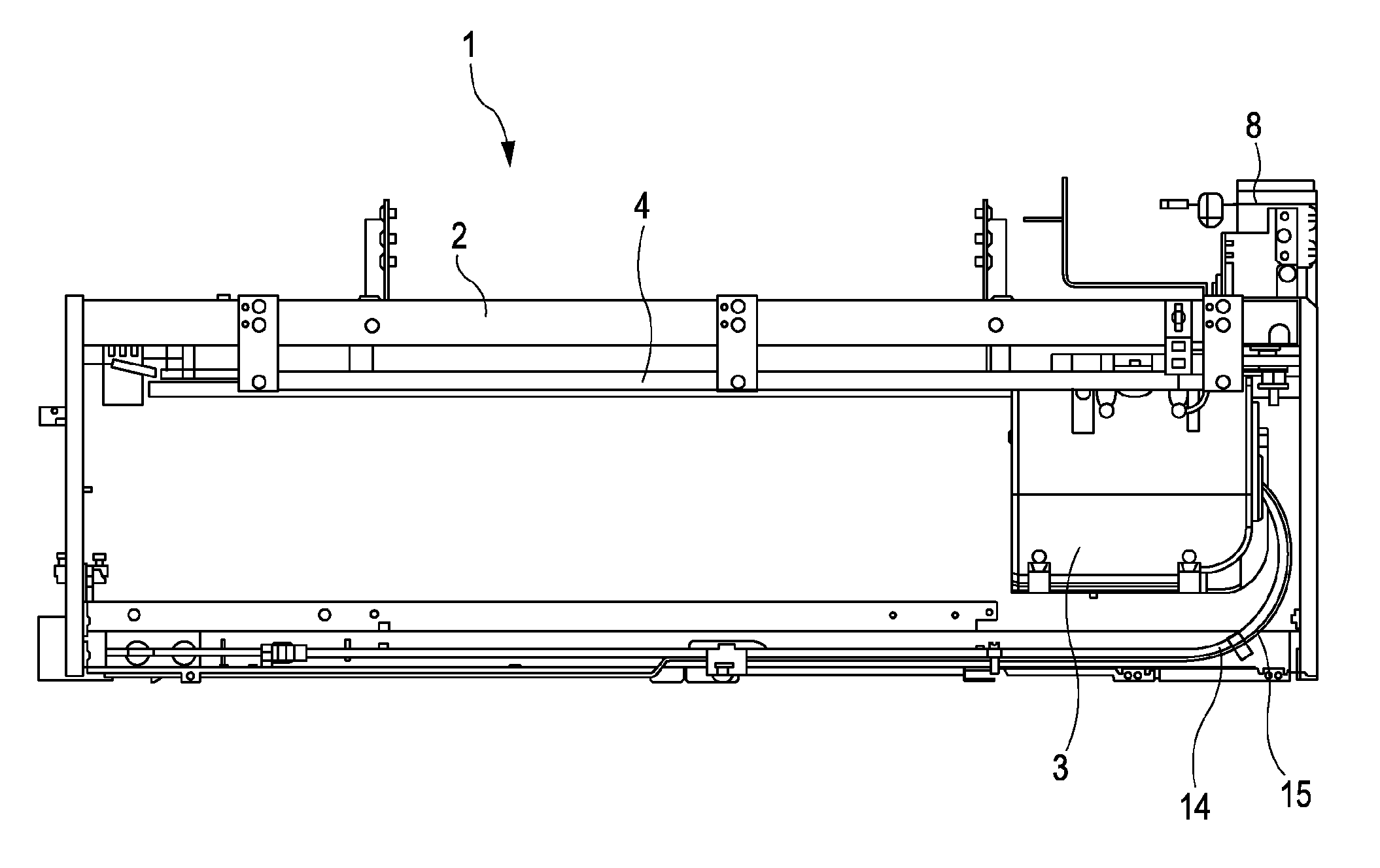
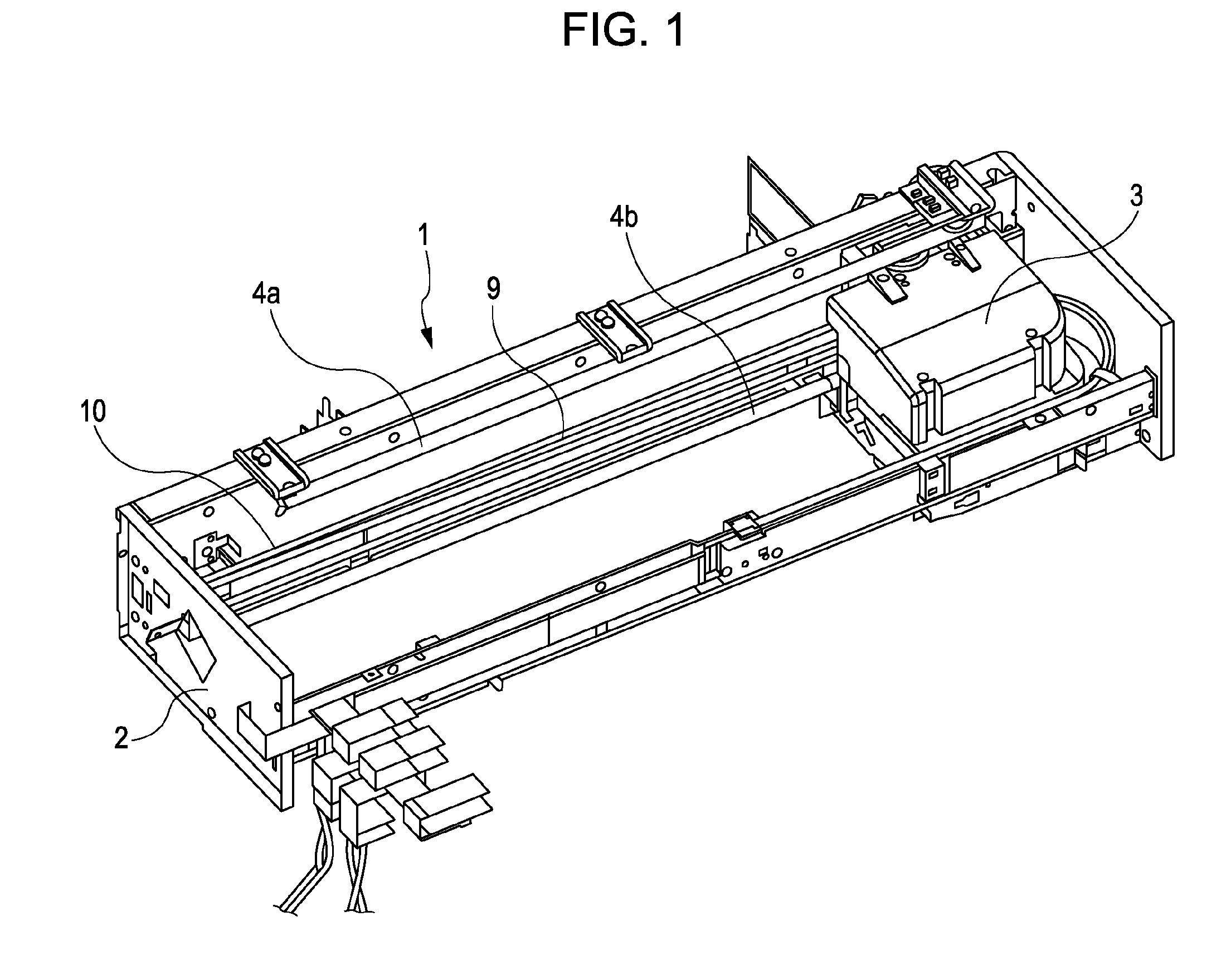
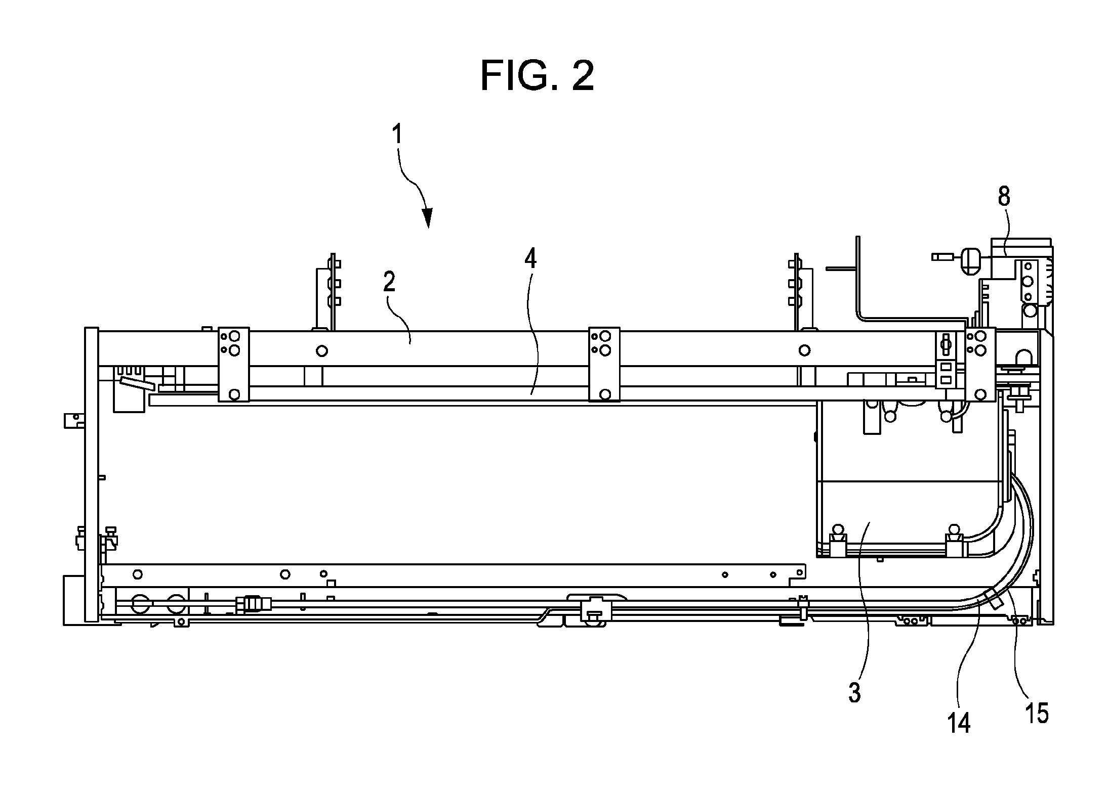
[0053]FIG. 1 is a perspective view showing a part of the internal structure of a printer 1, and FIG. 2 is a plan view of the printer 1. The printer 1 ejects ink, which is a type of liquid, onto a recording medium (a landing target), such as a recording sheet, cloth, or a film. In the printer 1, a carriage 3 (a type of head unit holding member) is installed in a frame 2 so as to be movable back and forth in a main scanning direction, i.e., a direction intersecting a recording-medium feeding ...


PUM


Abstract

A liquid ejecting head unit includes a liquid ejecting head having a nozzle forming surface provided with nozzle rows consisting of several rows of nozzles for ejecting liquid; and a head fixing member to which the liquid ejecting head is fixed with an intermediate member therebetween. The liquid ejecting head has an intermediate-member fixing portion to which the intermediate member is fixed. The intermediate member has a head-fixing-member bonding surface to be securely bonded to an intermediate-member bonding surface of the head fixing member with adhesive. The head-fixing-member bonding surface has a chamfered portion along at least a portion of an outer edge thereof, the chamfered portion being provided such that the distance from the intermediate-member bonding surface gradually increases from the inner side toward the outer side of the head-fixing-member bonding surface.

Description

[0001]The entire disclosure of Japanese Patent Application No: 2010-275451, filed Dec. 10, 2010 is expressly incorporated by reference herein.BACKGROUND[0002]1. Technical Field[0003]The present invention relates to a liquid ejecting head unit used in a liquid ejecting apparatus, such as an ink jet recording apparatus, and it also relates to a liquid ejecting apparatus and a method of producing the liquid ejecting apparatus. In particular, the invention relates to a liquid ejecting head unit, a liquid ejecting apparatus, and a method of producing the liquid ejecting apparatus in which a plurality of liquid ejecting heads are attached to a head fixing member in a removable manner.[0004]2. Related Art[0005]Liquid ejecting apparatuses include liquid ejecting heads that eject droplets of liquid. Various types of liquid can be ejected from the liquid ejecting heads. A typical example of the liquid ejecting apparatus is an image recording apparatus, such as an ink jet recording apparatus (...

Claims


Application Information

Patent Timeline
IPC IPC(8): B41J2/145B23P11/00
CPCB41J25/34Y10T29/49401B41J2202/19
Inventor HAGIWARA, HIROYUKIEGUCHI, MASAYUKIOTSUKI, KIMIYASUMOCHIZUKI, MASANORI
Owner SEIKO EPSON CORP
Learn More