Providing desired gloss to mixed media sheets

a technology of mixed media and desired gloss, applied in the direction of instruments, electrographic process equipment, optics, etc., can solve the problems of inconvenient or uneconomical use of these methods, inability to design imaging systems that can operate at multiples, and inability to achieve desired gloss. achieve the effect of productivity loss

Inactive Publication Date: 2012-06-14
EASTMAN KODAK CO
View PDF3 Cites 5 Cited by
  • Summary
  • Abstract
  • Description
  • Claims
  • Application Information

AI Technical Summary

Benefits of technology

[0016]A feature of the present invention is that it avoids the negative consequences of the other ways of regulating the heat delivered to the receiver sheets, the cost of mechanisms to permit for multiple speeds in the reproduction apparatus or for multiple nip force levels in the fixing apparatus, or the loss of productivity while waiting for a change in the temperature of the fixing members, or damage to the image in the return path.

Problems solved by technology

That is, multi-color images require a high degree of glossiness for a full, rich depth of color reproduction; on the other hand, since glossiness for black marking particle images can significantly impair legibility, a matte finish is preferred.
Therefore, receiver sheets of higher basis weight typically require more heat from the fixing apparatus to attain a given level of image glossiness.
The three methods of regulating the amount of heat that is delivered by a fixing apparatus to a receiver sheet have drawbacks that can make the use of these methods inconvenient or uneconomical.
For example, it is uneconomical or impractical to design an imaging system that can operate at multiple speeds.
It can also take an excessive amount of time to change the temperature of the fixing members, so that using a temperature change to regulate the heat delivery can cause an unacceptable loss of productivity for the reproductive apparatus.
The mechanism for changing the force in the nip between the fixing members is prohibitively expensive.
These limitations can cause the designers of the reproductive apparatus to provide another way of varying the heat that is delivered to the receiver sheet by the fixing apparatus.

Method used


Image

  • Providing desired gloss to mixed media sheets
  • Providing desired gloss to mixed media sheets
  • Providing desired gloss to mixed media sheets

Examples


Embodiment Construction

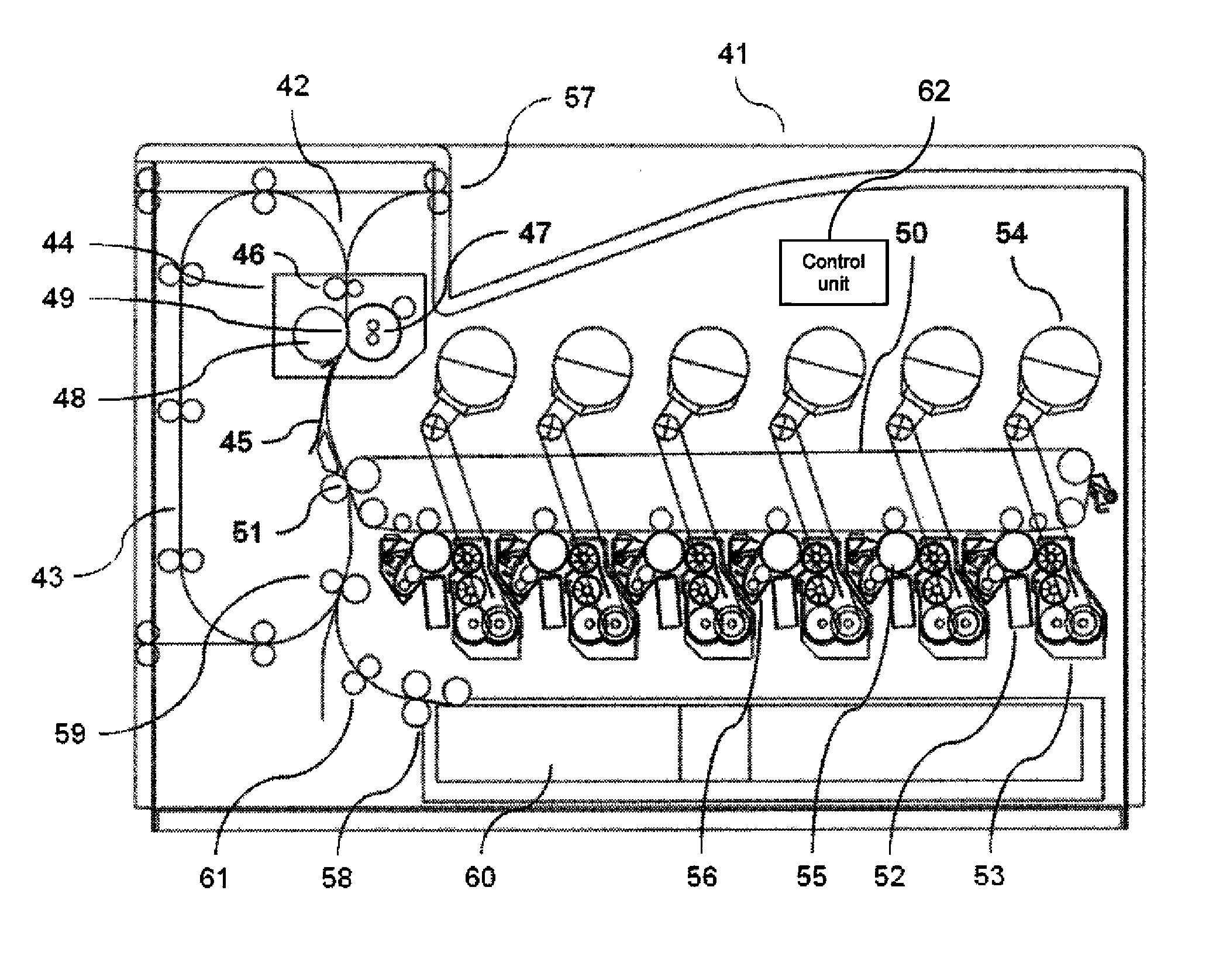
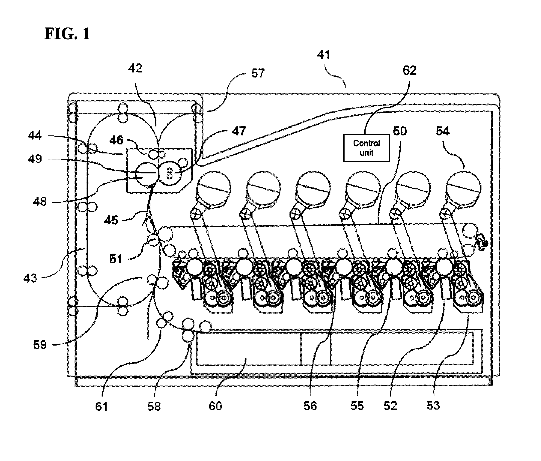
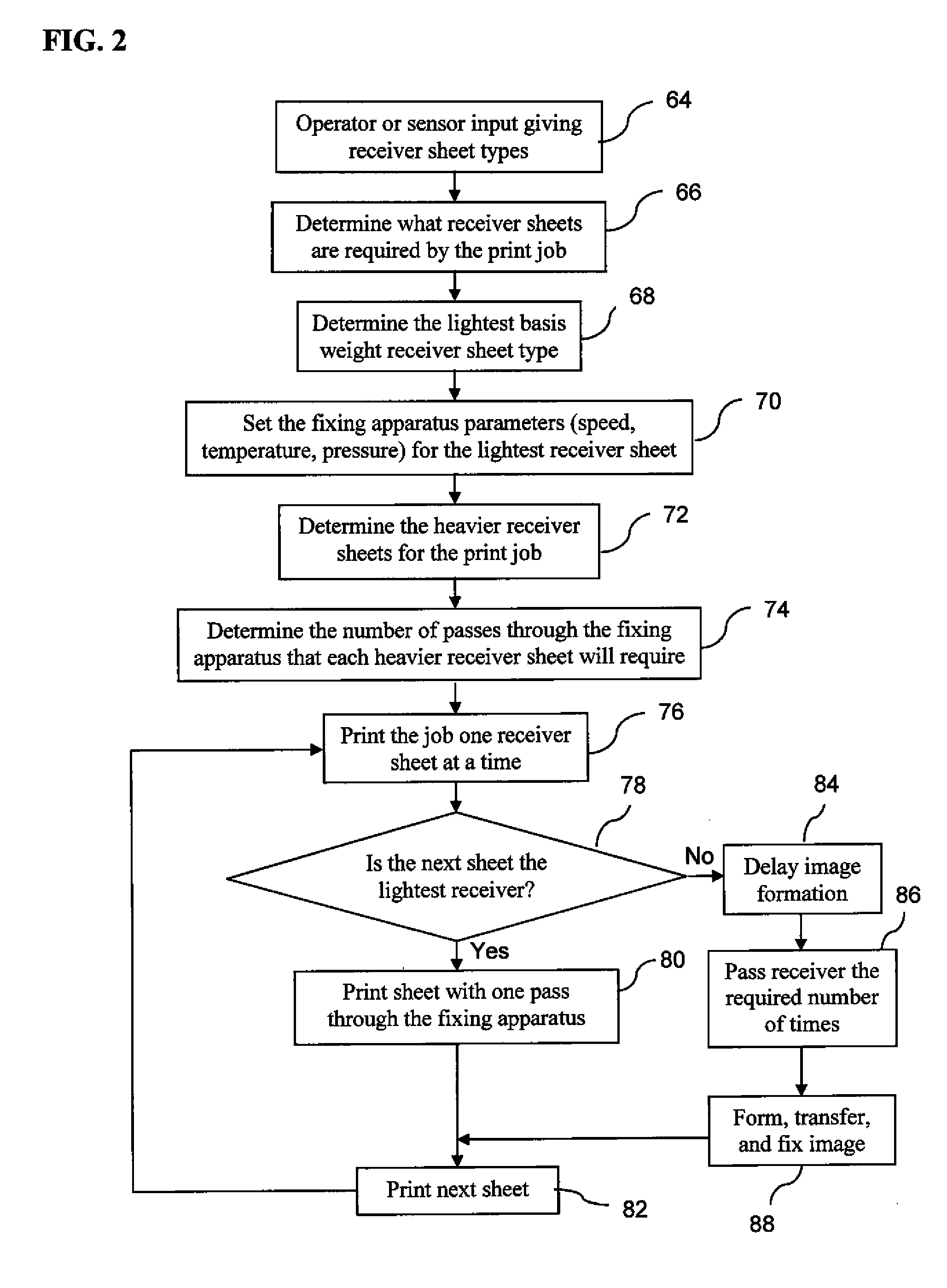
[0019]The response of a receiver sheet during the second pass through a fixing apparatus is different than during the first pass because the nature of the receiver sheet has been changed by the first pass. First, the receiver sheet will begin the second pass through the fixing apparatus at a higher temperature than the first pass because of the heat that was delivered to the sheet during the first pass. Second, if the receiver sheet is made of a hygroscopic material such as paper, the first pass through the fixing apparatus will drive moisture out of the receiver sheet so that on the second pass through the fixing apparatus, the heat capacity of the sheet will be less because of the reduced moisture content. For both reasons fixing the image on the second pass through the fixing apparatus will require less heat than did the fixing of the image on the first pass through the fixing apparatus. For high quality images, particularly photo-quality images, it is undesirable to pass the pri...


PUM


Abstract

Method of fixing marking particles to sheets having different basis weights in a continuous stream of receiver sheets, includes: providing two fixing members which engage each other to form a nip, at least one of the members being heated; and adjusting at least one parameter including temperature, speed, or pressure in the fixing nip, which will provide a predetermined gloss upon the sheet(s). The method further includes feeding the sheets of the higher basis weight through the nip so that the higher basis weight sheet(s) is fed more times through the nip than the other sheet(s); and applying marking particles to the prepared heavier basis weight sheets and passing them through the nip so that the gloss formed by the marking particles is substantially the same for heavier basis weight sheets as for lighter basis weight sheets.

Description

FIELD OF THE INVENTION[0001]This invention relates to maintaining a consistent image gloss when continuously printing on receivers of mixed basis weights.BACKGROUND OF THE INVENTION[0002]In typical commercial electrostatographic reproduction apparatus (copier / duplicators, printers, or the like), a latent image charge pattern is formed on a uniformly charged charge-retentive or photo-conductive member having dielectric characteristics (hereinafter referred to as the dielectric support member). Pigmented marking particles are attracted to the latent image charge pattern to develop such image on the dielectric support member. The developed image is transferred to a receiver member, such as a sheet of paper, transparency or other medium, in an electric field. After transfer, the receiver member bearing the transferred image is transported away from the dielectric support member, and the image is fixed (fused) to the receiver member by heat and pressure to form a permanent reproduction t...

Claims


Application Information

Patent Timeline
Patent Type & Authority Applications(United States)
IPC IPC(8): G03G15/20
CPCG03G15/657G03G15/2039G03G2215/00742
Inventor PICKERING, JERRY A.HURST, JAMES H.
Owner EASTMAN KODAK CO
Why Eureka
Try Eureka