Method of preheating a set of shell molds for lost-wax casting

a shell mold and lost wax technology, applied in the field of preheating the shell molds, can solve the problems of inability to change the temperature profile, the temperature of the shell mold within a single batch is not uniform, and the production management is not flexible, so as to reduce the waiting time for the change of the setpoint temperature and reduce the loss of productivity

Active Publication Date: 2017-07-04
SN DETUDE & DE CONSTR DE MOTEURS DAVIATION S N E C M A
View PDF8 Cites 0 Cited by
  • Summary
  • Abstract
  • Description
  • Claims
  • Application Information

AI Technical Summary

Benefits of technology

[0014]The method of the invention presents numerous advantages. In particular, having recourse to a plurality of unit electric furnaces makes great flexibility possible in managing the preheating of the set of N shell molds. Specifically, since the waiting time for changes in setpoint temperature is shortened, it is possible to produce shell molds that have been preheated with different temperature profiles (with the temperature profile being adapted to each shell mold), without any loss of productivity, and to do so in simultaneous manner.
[0015]Furthermore, having recourse to unit electric furnaces for preheating shell molds makes it possible to reduce considerably the difference in temperature between a preheated shell mold and the setpoint temperature (with a maximum variation of plus or minus 5° C. relative to the setpoint temperature). Any risk of giving rise to metallurgical defects in the fabricated parts are thus reduced.
[0016]The unit electric furnaces have relatively little inertia (compared with prior art gas-fired tunnel kilns), thus making it possible to have better temperature control over the method by using regulation that is accurate and repeatable. Furthermore, the duration of a preheating cycle is shorter than the duration of a preheating cycle using a prior art gas-fired tunnel kiln.
[0017]Even in the event of one of the unit electric furnaces failing, the production of preheated shell molds is not interrupted (since the other unit electric furnaces remain operational), thereby considerably reducing the impact of a failure on the production line. In particular, a failure does not lead to a total stop in production.
[0018]Finally, compared with a gas-fired tunnel kiln, unit electric furnaces present maintenance costs that are low, they do not give off pollutants of the carbon dioxide type, and they present energy costs that are much lower (as much as 80% lower). They can easily be moved within the installation, when necessary. It should also be observed that the shell molds are positioned in these unit electric furnaces on stationary bed plates, thereby limiting any risk of breaking.
[0019]The number n of unit electric furnaces may be less than the number N of shell molds for preheating. Specifically, the method of the invention makes it possible to produce preheated shell molds at an industrial rate.

Problems solved by technology

Such an operation of preheating shell molds by means of gas-fired tunnel kilns nevertheless presents numerous drawbacks.
In particular, having recourse to organization of that type leaves no flexibility in managing production; a large quantity of shell molds are charged and it is not possible to change a temperature profile for a given batch (e.g. changing from a preheating temperature of 1100° C. to 950° C. on going from one shell mold to another).
It has also been found that the temperatures of shell molds within a single batch are not uniform on leaving gas furnaces, with temperature variations of plus or minus 15° C. relative to the setpoint temperature.
Such non-uniformity may have the consequence of leading to metallurgical defects (of the crack type) in the parts that are to be fabricated.
Furthermore, having recourse to carriages that are movable in gas-fired tunnel kilns presents several disadvantages, such as considerable labor for installing and removing shell molds and a non-negligible risk of one or more shell molds breaking in such kilns.
Finally, gas-fired tunnel kilns have maintenance costs that are high, due in particular to the length of time needed to act on them, during which time the production means are completely unavailable.

Method used


Image

  • Method of preheating a set of shell molds for lost-wax casting
  • Method of preheating a set of shell molds for lost-wax casting
  • Method of preheating a set of shell molds for lost-wax casting

Examples


Embodiment Construction

[0029]The invention relates to making metal parts by lost-wax casting, e.g. metal blades for a low pressure turbine or ring sectors for an aviation turbine engine.

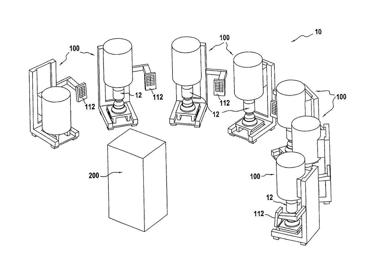
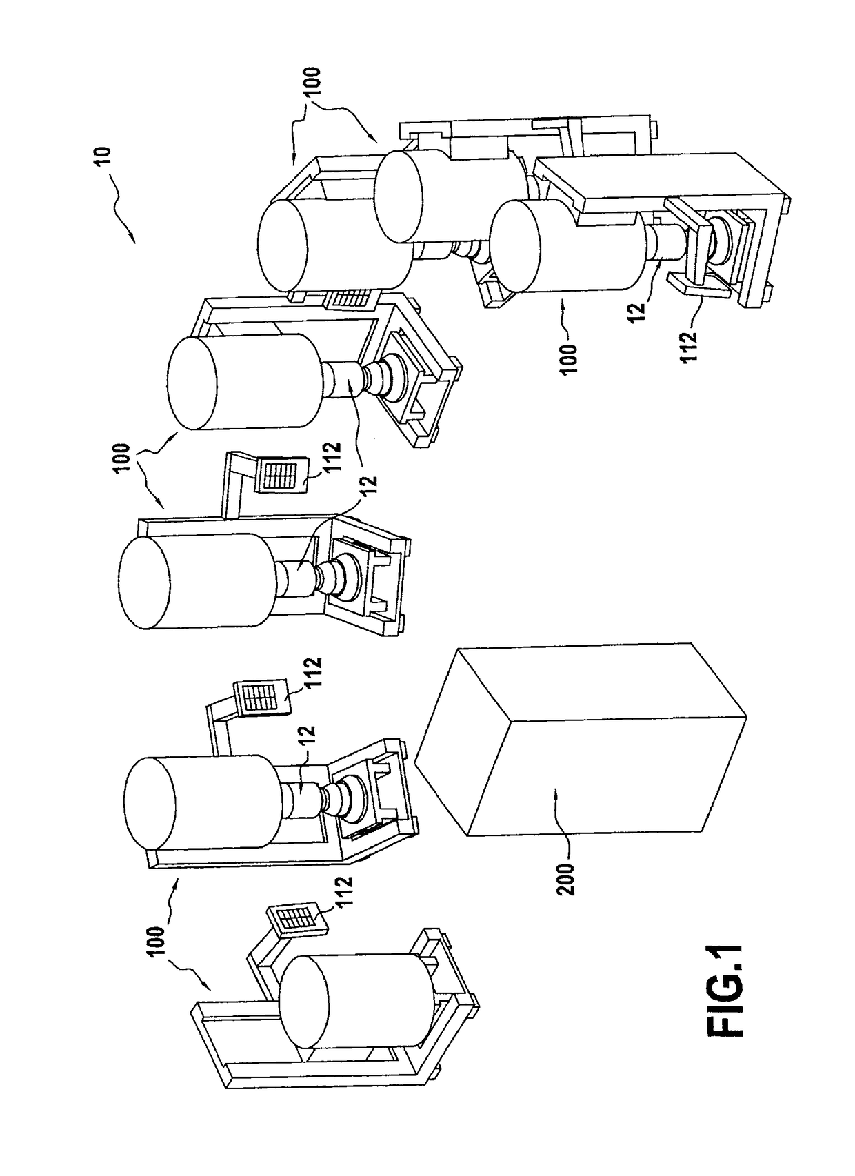
[0030]FIG. 1 is a diagram showing an embodiment of a preheater installation 10 for performing the method of the invention for preheating a set of N shell molds 12, the shell molds 12 being used for making such metal parts by lost-wax casting.

[0031]In known manner, the shell molds are fabricated around wax models of the metal parts that are to be made by performing alternating and repeated operations of dipping in a ceramic slip and of stuccoing ceramic materials. The shell molds are then fired in a kiln in order to enable them to acquire the mechanical strength needed for withstanding the casting of molten metal. In order to avoid any thermal shock between the molten metal that is poured at very high temperature (typically higher than 1000° C.) and the shell molds that receive the metal, the molds are subjected to a prehea...


PUM

PropertyMeasurementUnit
temperatureaaaaaaaaaa

Abstract

A method including preheating a set of N shell molds for lost-wax casting, where the method can comprise: individually charging shell molds into n unit electric furnaces, each of which has previously been preheated to an initial loading temperature; starting a predefined preheating cycle for each shell mold charged in the unit electric furnaces, with a preheating cycle comprising raising the temperature of the furnace in compliance with a predefined ramp up to a predetermined setpoint temperature, and holding the furnace at the setpoint temperature for a predetermined duration; and at the end of each preheating cycle, unloading the shell mold in question and repeating the two preceding operations for another non-preheated shell mold.

Description

BACKGROUND OF THE INVENTION[0001]The present invention relates to the general field of making metal parts by a lost-wax casting method. The invention relates more particularly to preheating the shell molds that are used in such a casting method.[0002]The lost-wax casting method consists of using wax to make an exact replica of the part that is to be fabricated. This model is covered by alternating and repeated dipping operations for building up a plurality of layers of ceramic in order to form a shell mold. After the wax has been eliminated, the shell mold is shaped with a cavity in which the smallest details of the part to be fabricated are reproduced. The “unwaxed” shell mold is then fired in a kiln, thereby giving it the mechanical properties it needs prior to having molten metal poured therein.[0003]Furthermore, in order to avoid a thermal shock between the molten metal that is poured in at very high temperature (higher than 1000° C.) and the shell mold that receives it, the mol...

Claims


Application Information

Patent Timeline
Patent Type & Authority Patents(United States)
IPC IPC(8): B22D45/00F27D3/00B22C9/12B22C9/04F27D1/18F27D11/00
CPCB22D45/00B22C9/04B22C9/12F27D1/1858F27D3/0021F27D11/00
Inventor CALERO, PATRICK ALBERTLALLEMENT, BERNARD LOUISTENNE, SERGERAPPART, YVAN
Owner SN DETUDE & DE CONSTR DE MOTEURS DAVIATION S N E C M A
Why Eureka
Try Eureka