Method and apparatus for attaching soft tissue to bone

a surgical method and bone technology, applied in the field of surgical methods and equipment, can solve the problems of limited hole technology, difficult and/or inconvenient for surgeons to knot the suture, and significant limitation

Active Publication Date: 2012-06-14
REDYNS MEDICAL
View PDF11 Cites 14 Cited by
  • Summary
  • Abstract
  • Description
  • Claims
  • Application Information

AI Technical Summary

Benefits of technology

[0015]The inventive concepts disclosed herein include a new suture anchor system for attaching soft tissue to bone which permits the surgeon to attach one or more sutures to the body of the suture anchor after the body of the suture anchor has been deployed in bone, thereby allowing the surgeon to customize the manner in which the soft tissue is attached to the bone. The inventive concepts disclosed herein provide a surgeon with the ability to modify a soft tissue repair construct, in part or in whole, without removing any previously-deployed anchors forming part of the repair construct. Furthermore, the present invention permits the soft tissue to be attached to the bone without tying a knot in the suture.

Problems solved by technology

This can be a significant limitation, since in many circumstances the surgeon may wish to adjust a procedure in response to tissue conditions which may only become apparent after the procedure has begun.
In addition to the foregoing, it can be difficult and / or inconvenient for the surgeon to knot the suture when physical access to the surgical site is limited, e.g., as in the case of an arthroscopic procedure.
Nonetheless, all existing technology is limited to a hole through which suture must be threaded.
Limitations of this design include the fact that suture may not be removed easily from the hole after it has been threaded through.
Additionally, due to the fact that suture will typically have a curved needle attached to its leading end to facilitate suture passing, it is unwise to pass a second or third segment of suture through the same hole in the implant as the surgeon may risk damaging the original strand with the sharp point of the curved needle.

Method used


Image

  • Method and apparatus for attaching soft tissue to bone
  • Method and apparatus for attaching soft tissue to bone
  • Method and apparatus for attaching soft tissue to bone

Examples


Embodiment Construction

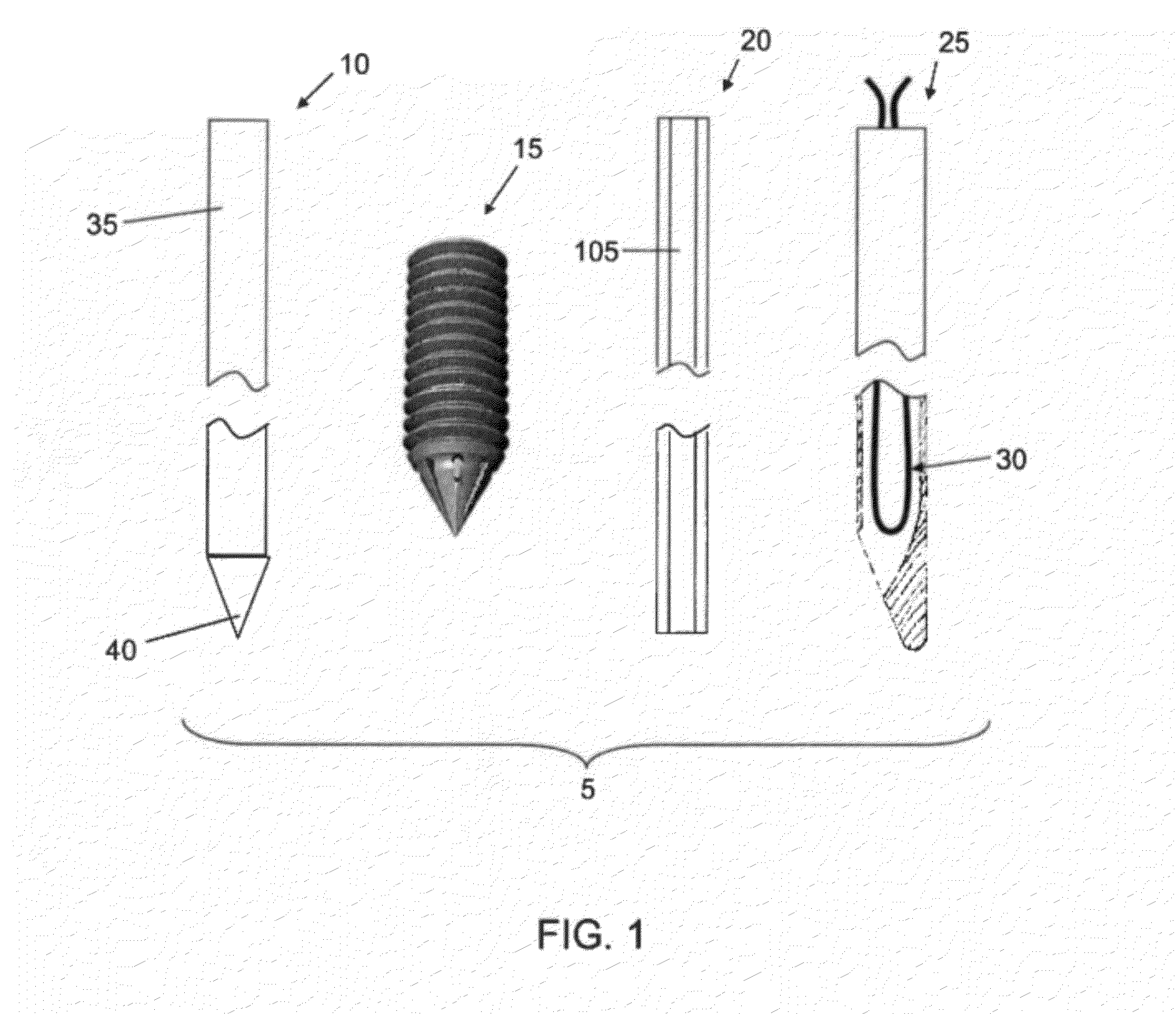
[0071]Looking first at FIG. 1, there is shown a suture anchor system 5 formed in accordance with the present invention. Suture anchor system 5 generally comprises a pilot drill 10, an anchor 15, a driver 20 and a suture threader 25 carrying a suture 30 therein.

[0072]Still looking now at FIG. 1, pilot drill 10 is a conventional pilot drill of the sort used to form a pilot hole in bone. Pilot drill 10 generally comprises a shaft 35 terminating in a distal point 40.

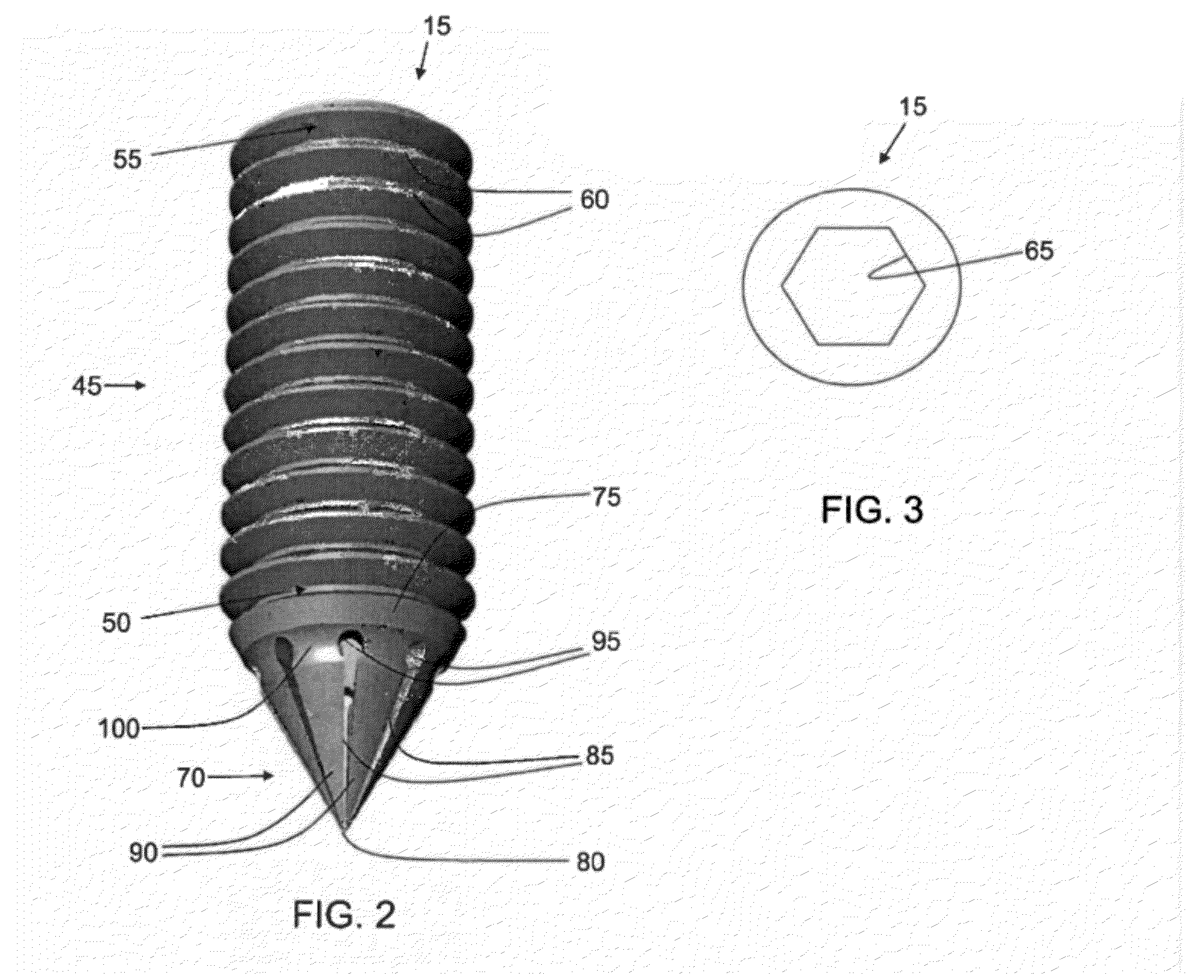
[0073]Looking next at FIGS. 1-3, anchor 15 generally comprises a cylindrical body 45 having a distal end 50 and a proximal end 55. Screw threads 60 extend from distal end 50 to proximal end 55. A non-circular (e.g., hexagonal) bore 65 extends from distal end 50 to proximal end 55. Cylindrical body 45 is substantially rigid.

[0074]A hollow nose cone 70 is secured to distal end 50 of cylindrical body 45. Hollow nose cone 70 comprises a generally conical shape, with its base 75 being secured to distal end 50 of body 45 and with ...


PUM


Abstract

A repair system comprising at least one anchor, screw, or plate comprising a body and a suture capture element formed in the body for attaching at least one suture to the anchor, screw, or plate. The suture capture element being configured so as to permit the suture to be snared by the suture-capture element after the anchor, screw, or plate has been attached to bone.

Description

CROSS REFERENCE TO RELATED APPLICATIONS[0001]This application claims benefit to U.S. Provisional Application Ser. No. 61 / 374,536, filed Aug. 17, 2010, and U.S. Provisional Application Ser. No. 61 / 443,129, filed Feb. 15, 2011, each of which is hereby incorporated herein in its entirety.BACKGROUND OF THE INVENTION[0002]1. Field of the Invention[0003]This invention relates to surgical methods and apparatus in general, and more particularly to surgical methods and apparatus for attaching soft tissue to bone and for reducing and fixing fractured bones.[0004]2. Brief Description of Related Art[0005]In many situations soft tissue may need to be attached (or re-attached) to bone. By way of example but not limitation, a ligament or tendon may have been detached from bone as the result of injury and / or accident, and appropriate repair may require re-attaching the ligament or tendon to its host bone. By way of further example but not limitation, some surgical procedures may require the suspens...

Claims


Application Information

Patent Timeline
Patent Type & Authority Applications(United States)
IPC IPC(8): A61B17/80
CPCA61B17/0401A61F2002/0882A61B17/282A61B17/80A61B17/8057A61B17/8605A61B17/863A61B17/8635A61B17/8645A61B17/8875A61B2017/0414A61B2017/044A61B2017/0446A61B2017/0448A61B2017/045A61B2017/0458A61B2017/2926A61F2/0805A61F2/0811A61B17/0485A61B17/04A61B17/062A61B17/56A61B17/86
Inventor SNYDER, NATHANROHLINGER, GEORGE J.
Owner REDYNS MEDICAL
Why Eureka
Try Eureka