Gas turbine engine control using acoustic pyrometry

a technology of acoustic pyrometry and a turbine engine, which is applied in the direction of instruments, horology, cathode-ray oscilloscopes, etc., can solve the problems of uncertainties in relation to temperature calculation for controlling the engin

Active Publication Date: 2012-06-14
SIEMENS ENERGY INC
View PDF0 Cites 102 Cited by
  • Summary
  • Abstract
  • Description
  • Claims
  • Application Information

AI Technical Summary

Problems solved by technology

Such monitoring systems generally require locating thermocouples at different fixed axial locations along the exhaust flow, which may introduce uncertainties in relation to temperature calculations for controlling the engine as conditions affecting operation of the engine change, such as a varying load condition on the engine.

Method used


Image

  • Gas turbine engine control using acoustic pyrometry
  • Gas turbine engine control using acoustic pyrometry
  • Gas turbine engine control using acoustic pyrometry

Examples


Embodiment Construction

[0016]In the following detailed description of the preferred embodiment, reference is made to the accompanying drawings that form a part hereof, and in which is shown by way of illustration, and not by way of limitation, a specific preferred embodiment in which the invention may be practiced. It is to be understood that other embodiments may be utilized and that changes may be made without departing from the spirit and scope of the present invention.

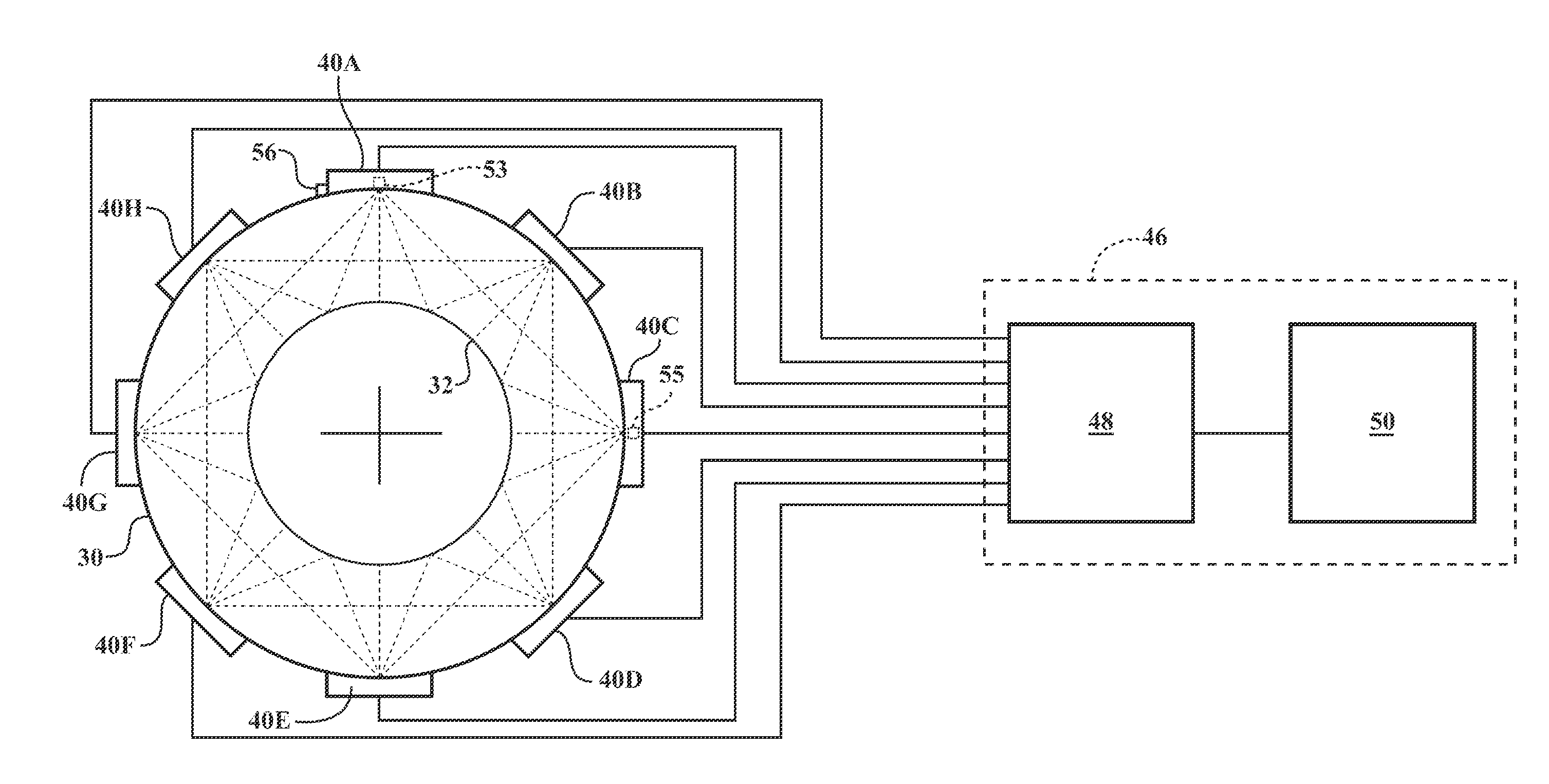
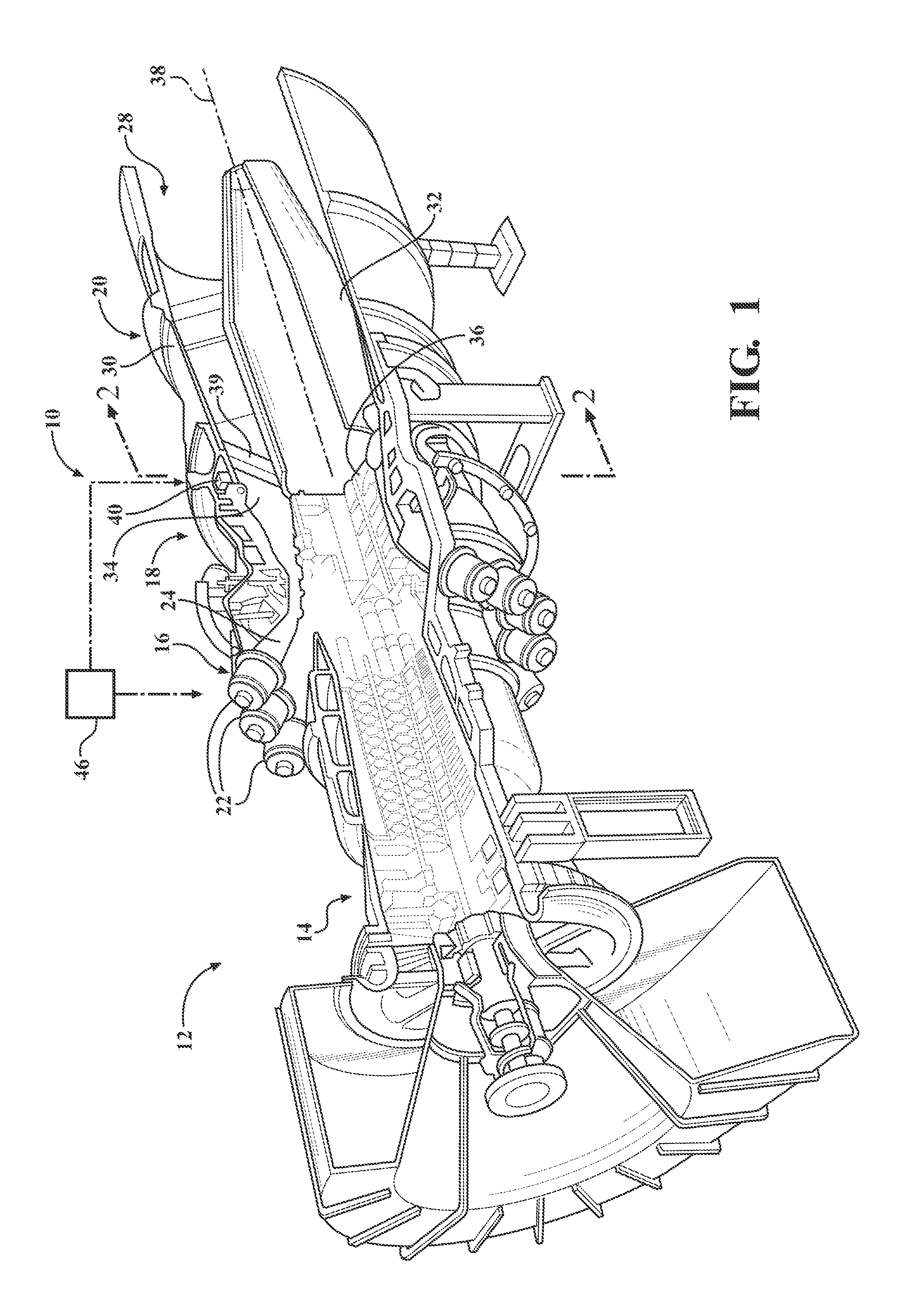
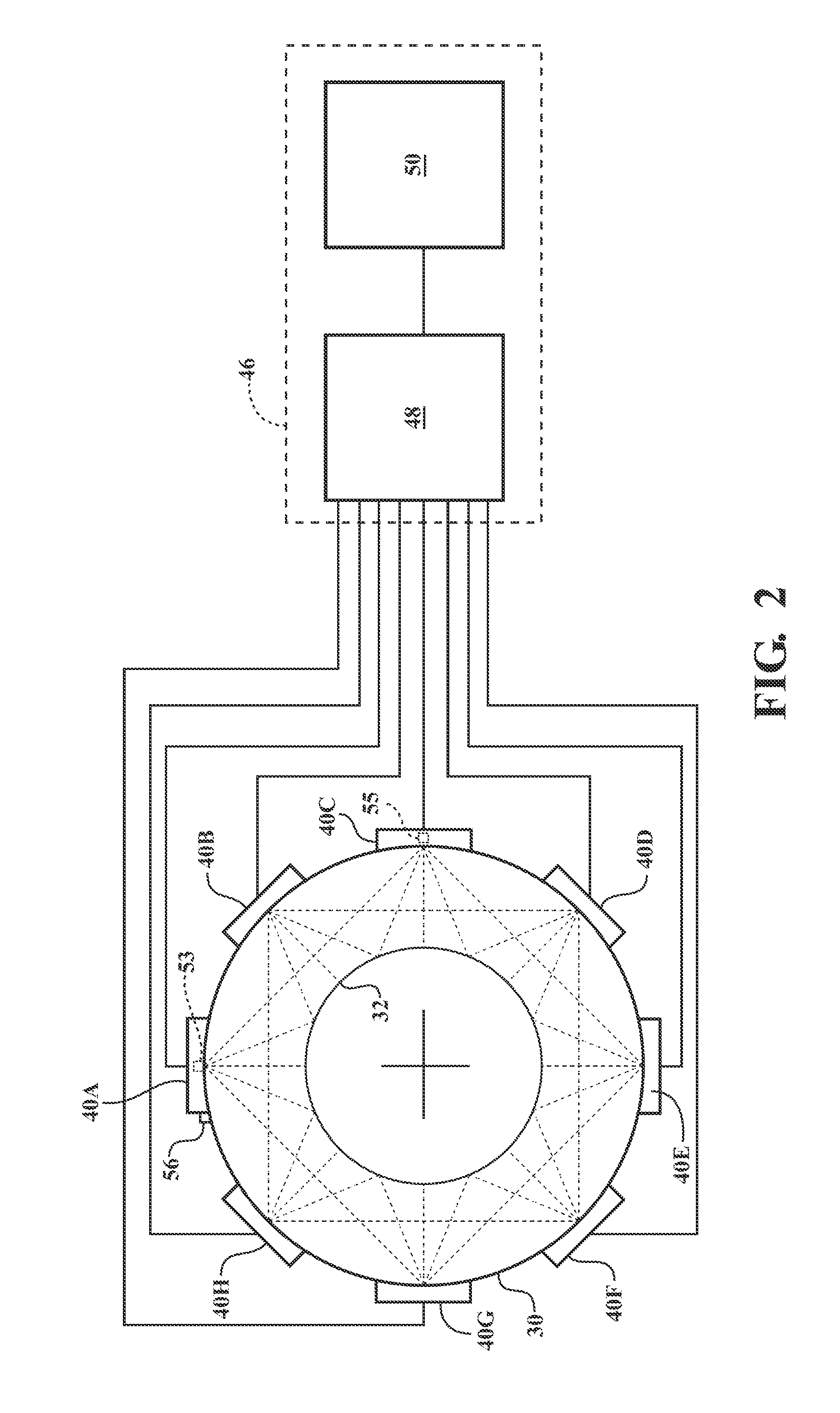
[0017]Referring to FIG. 1, embodiments of the invention are directed to an acoustic pyrometer system 10 that may be incorporated in a gas turbine engine 12 and to methods of using the acoustic pyrometer system 10 to determine temperatures at predetermined locations in the engine 12 and to control an operation of the engine 12. Aspects of the invention will be explained in connection with various possible configurations, but the detailed description is intended only as exemplary.

[0018]As illustrated in FIG. 1, the turbine engine 12 genera...


PUM

PropertyMeasurementUnit
frequenciesaaaaaaaaaa
temperatureaaaaaaaaaa
time-of-flightaaaaaaaaaa

Abstract

A method and apparatus for operating a gas turbine engine including determining a temperature of a working gas at a predetermined axial location within the engine. Acoustic signals are transmitted from a plurality of acoustic transmitters and are received at a plurality of acoustic receivers. Each acoustic signal defines a distinct line-of-sound path from one of the acoustic transmitters to an acoustic receiver corresponding to the line-of-sound path. A time-of-flight is determined for each of the signals traveling along the line-of-sound paths, and the time-of-flight for each of the signals is processed to determine a temperature in a region of the predetermined axial location.

Description

FIELD OF THE INVENTION[0001]The present invention relates to temperature measurement in turbine engines and, more particularly, to determination of temperature using acoustic measurements to control a gas turbine engine.BACKGROUND OF THE INVENTION[0002]Combustion turbines, such as gas turbine engines, generally comprise a compressor section, a combustor section, a turbine section and an exhaust section. In operation, the compressor section can induct and compress ambient air. The combustor section generally may include a plurality of combustors for receiving the compressed air and mixing it with fuel to form a fuel / air mixture. The fuel / air mixture is combusted by each of the combustors to form a hot working gas that may be routed to the turbine section where it is expanded through alternating rows of stationary airfoils and rotating airfoils and used to generate power that can drive a rotor. The expanding gas exiting the turbine section can be exhausted from the engine via the exha...

Claims


Application Information

Patent Timeline
Patent Type & Authority Applications(United States)
IPC IPC(8): F02C9/28G01K13/00G01K11/24
CPCF02C9/28G01K11/24F05D2260/80
Inventor BUNCE, RICHARD H.DESILVA, UPUL P.
Owner SIEMENS ENERGY INC
Why Eureka
Try Eureka