Oil separator

a technology of oil separator and oil tank, which is applied in the direction of separation process, refrigeration components, lighting and heating apparatus, etc., can solve the problems of particularly low heat exchange performance of refrigerating devices, and achieve the effect of simple and small structure, high oil separation efficiency

Active Publication Date: 2012-06-21
KOBE STEEL LTD
View PDF2 Cites 15 Cited by
  • Summary
  • Abstract
  • Description
  • Claims
  • Application Information

AI Technical Summary

Benefits of technology

[0007]In consideration of the above problems, an object of the present invention is to provide an oil separator having high oil separation efficiency with a simple and small structure.

Problems solved by technology

A heat exchanger (a condenser) of a refrigeration device particularly shows an extremely low heat exchanging performance when a mixed amount of oil exceeds a certain amount.

Method used


Image

  • Oil separator
  • Oil separator
  • Oil separator

Examples


Embodiment Construction

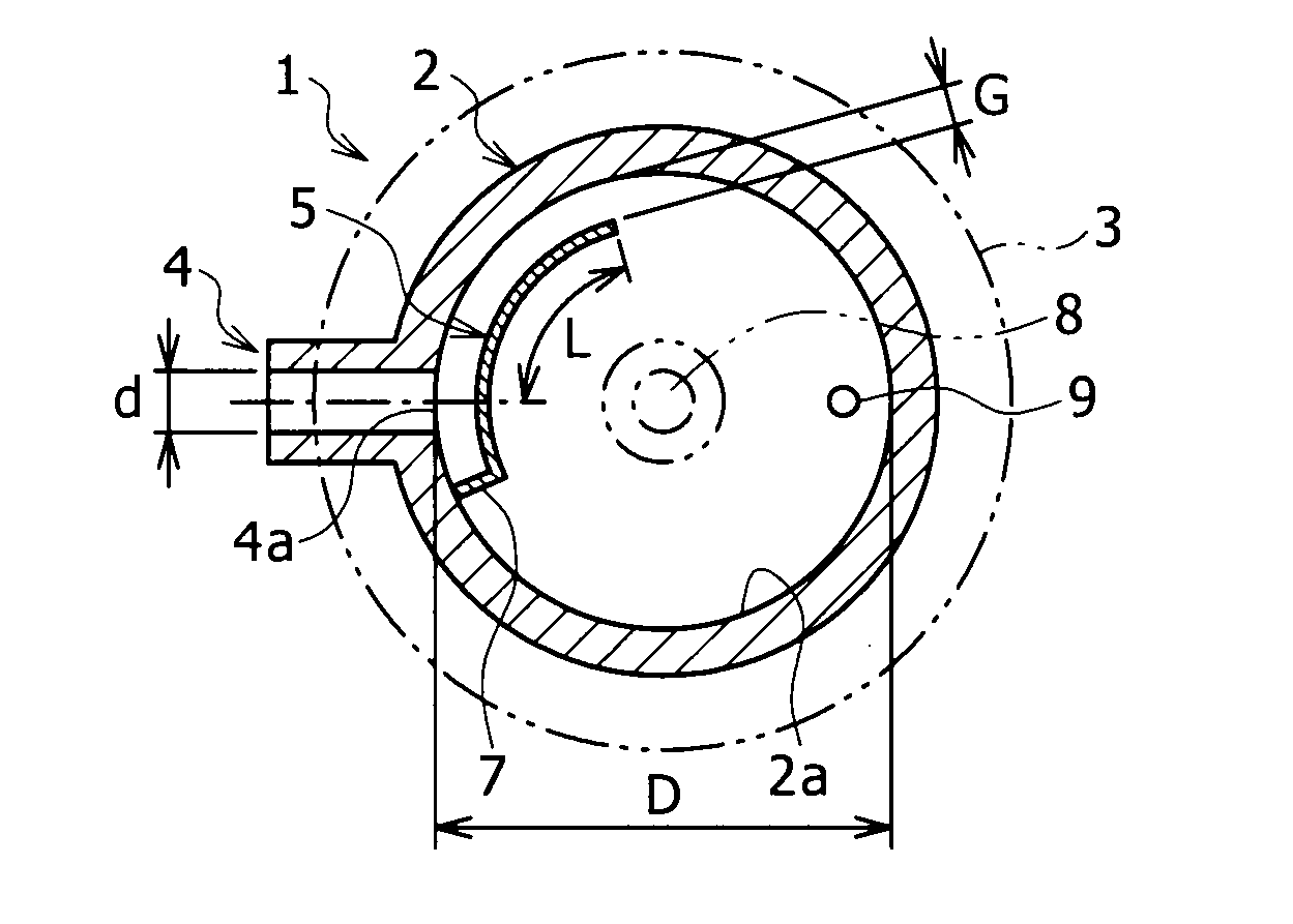
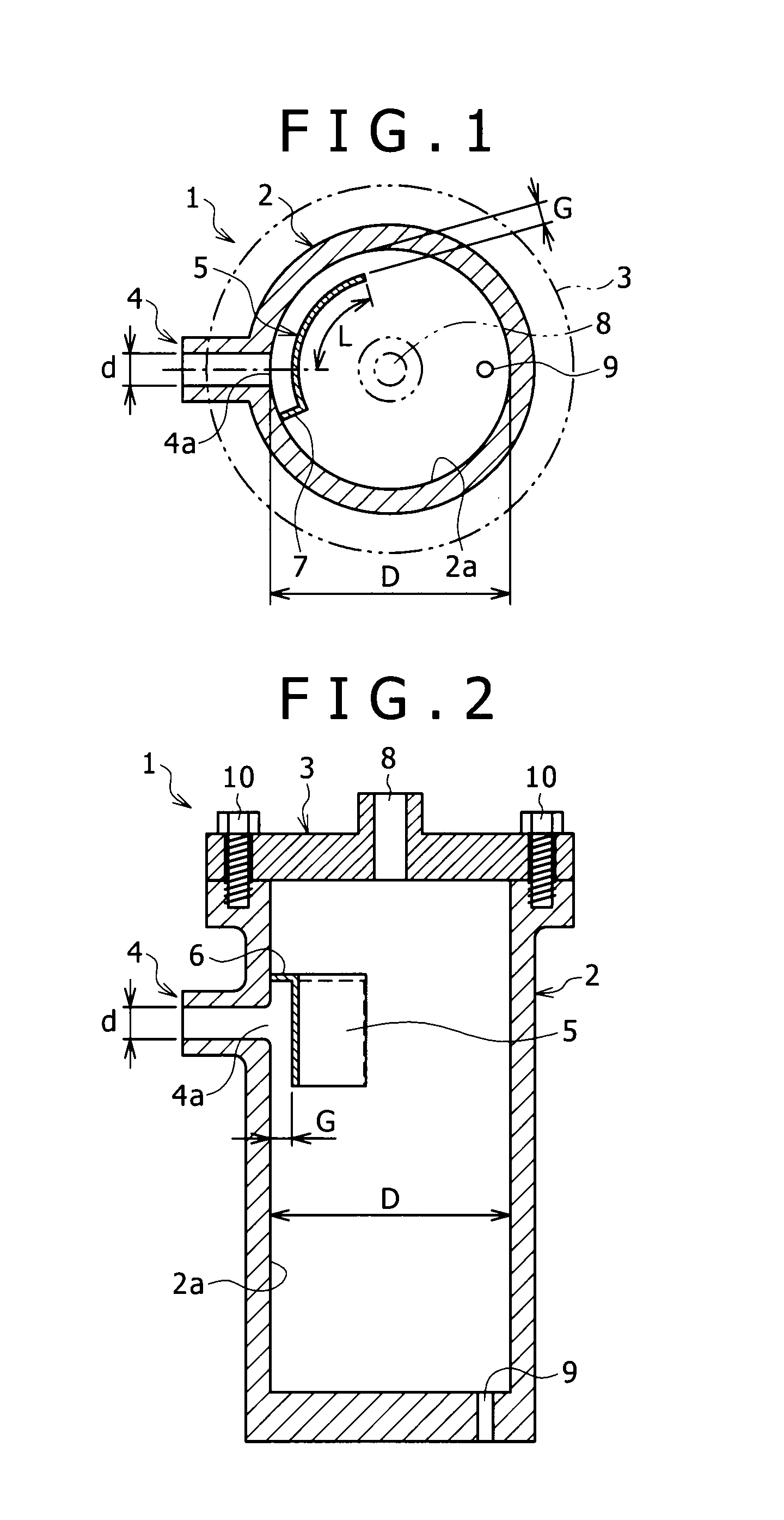
[0021]Hereinafter, embodiments of the present invention will be described with reference to drawings. FIGS. 1 and 2 show an oil separator 1 of a first embodiment of the present invention. The oil separator 1 is mainly used to separate cooling oil from gas discharged from an oil cooling type screw compressor (not shown), and intended to be arranged between the oil cooling type screw compressor and a condenser (a heat exchanger) in a refrigeration device.

[0022]The oil separator 1 has a container main body 2 formed into an upright bottomed cylinder shape having a diameter D, and a lid body 3 for sealing an upper end opening of the container main body 2. An introduction flow channel 4, which introduces the discharged gas, is radially disposed on the container main body 2, that is, disposed vertically on a side wall of the container main body 2, and an opening 4a having an inner diameter d is formed in an inner wall 2a of the container main body 2.

[0023]A partition wall member 5 extendin...


PUM

PropertyMeasurementUnit
widthaaaaaaaaaa
inner diameteraaaaaaaaaa
lengthaaaaaaaaaa

Abstract

An oil separator has a container main body and an flow channel. A partition wall member faces the opening of the flow channel and extends along a wall of the container main body. An upper end member seals the space between the upper end of the partition wall member and the container main body. A side end member seals a space between one side end of the partition wall member and the wall of the container main body. A gap between the partition wall member and the wall of the container main body is narrower than an inner diameter of the flow channel and is largest at an open side end. An outer circumference of the partition wall member is longer than half of the inner diameter of the flow channel and shorter than half of the circumferential length of the inner wall of the container main body.

Description

BACKGROUND OF THE INVENTION[0001]1. Field of the Invention[0002]The present invention relates to an oil separator, particularly to an oil separator suitable for separating cooling oil from gas discharged from an oil cooling type compressor.[0003]2. Description of the Related Art[0004]In general, in facility using an oil cooling type compressor, an oil separator that blows gas discharged from an oil cooling type compressor into a container so as to inertially separate or centrifugally separate cooling oil contained in the discharged gas is widely used.[0005]Japanese Unexamined Patent Application Publication No. S57(1982)-127883 describes an invention of an oil separator in which a fluid inlet is provided in an upper part of a side wall of a vertical type cylindrical container, a fluid outlet is provided in an upper lid of the cylindrical container, and an oil separation element is provided so as to cover the fluid outlet, wherein an inner cylinder is provided so as to surround the oi...

Claims


Application Information

Patent Timeline
Patent Type & Authority Applications(United States)
IPC IPC(8): B01D45/08
CPCF25B43/02F25B2500/01F25B2400/02
Inventor YOSHIMURA, SHOJIMAEDA, MICHIKOAMANO, YASUSHI
Owner KOBE STEEL LTD
Why Eureka
Try Eureka