Electromechanical actuator

a technology of electromechanical actuators and actuators, applied in the direction of dynamo-electric machines, electrical devices, gearing, etc., can solve the problems of increasing increasing the weight increasing the complexity so as to reduce the size of the structure of the electromechanical actuator, simplify the structure and make it small.

Active Publication Date: 2015-04-09
NABLESCO CORP
View PDF12 Cites 11 Cited by
  • Summary
  • Abstract
  • Description
  • Claims
  • Application Information

AI Technical Summary

Benefits of technology

[0009]The present invention is for solving the foregoing problem, and an object thereof is to provide an electromechanical actuator whose structure is simplified and made small, and in which, even if a jammed state occurs in one screw mechanism, the other screw mechanism can move an output portion back and forth with respect to a housing.
[0015]Accordingly, with this configuration, even if the first screw mechanism that is mainly used to move the output portion back and forth during normal operation enters a jammed state, the output portion can be moved with respect to the housing by the second screw mechanism. Moreover, the structure for moving the output portion back and forth when in a jammed state as described above is realized with a relatively small and simple structure configured to include the pair of rotor portions that are provided with respect to the common stator, the first screw mechanism, the second screw mechanism, and the like. For this reason, simplification and a size reduction of the structure of the electromechanical actuator will be achieved.
[0016]Accordingly, with this configuration, it is possible to provide an electromechanical actuator whose structure is simplified and made small, and in which, even if a jammed state occurs in one of the screw mechanisms, the output portion can be moved back and forth with respect to the housing by the other screw mechanism.
[0026]With this configuration, since the fourth screw portion can be accommodated within the rotation member, the size of the electromechanical actuator can be further reduced.
[0028]With this configuration, since the sliding portion and the fourth screw portion can be arranged so as to be aligned in the axial direction, the axial length of the electromechanical actuator can be reduced.

Problems solved by technology

For this reason, the structure of this electromechanical actuator will become complicated and large.
The weight of the electromechanical actuator will also increase with an increase in the size of the structure.

Method used


Image

  • Electromechanical actuator
  • Electromechanical actuator
  • Electromechanical actuator

Examples


Embodiment Construction

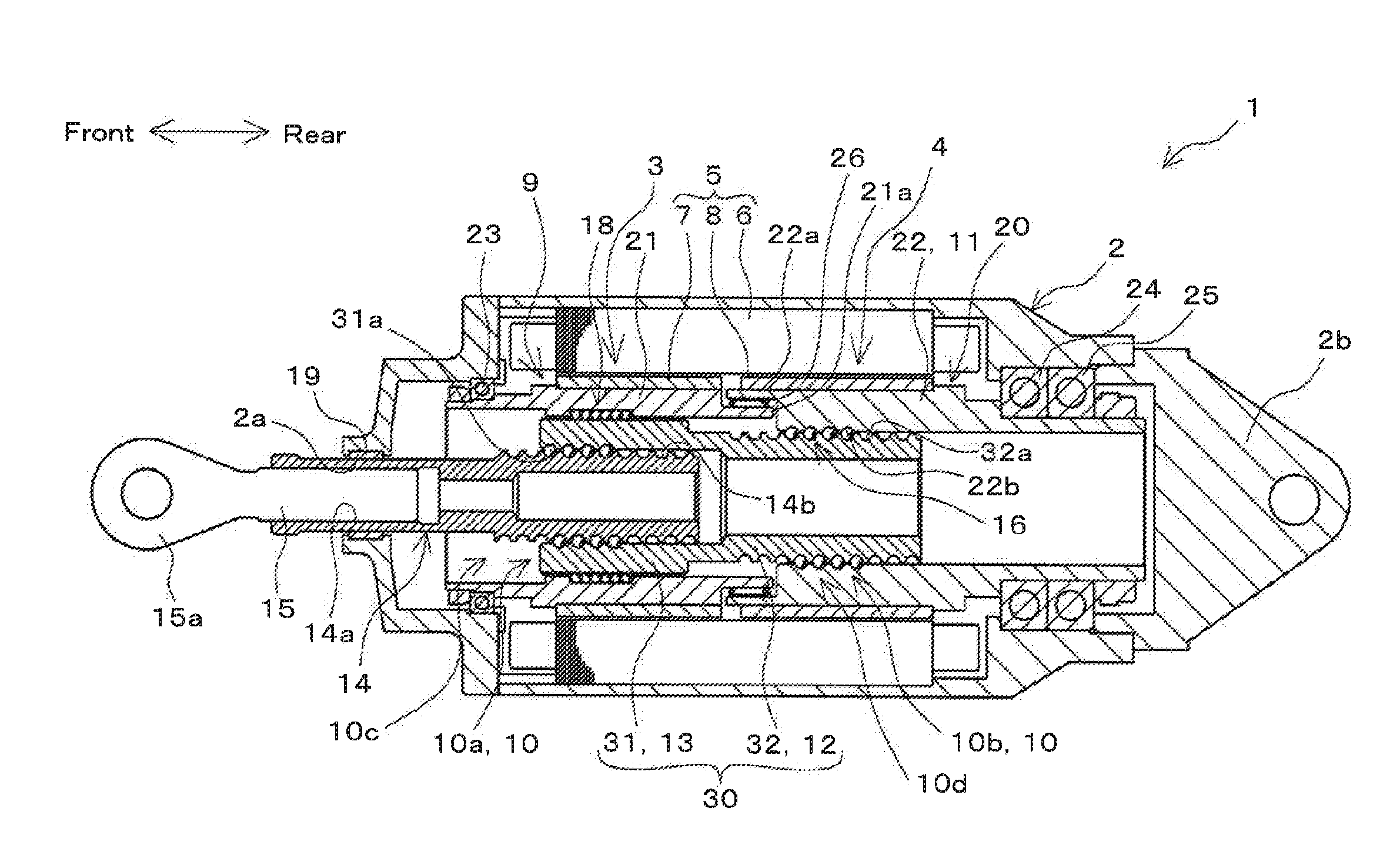
[0038]Hereinafter, a mode for carrying out the present invention will be described with reference to the drawings. In the following embodiment, an exemplary mode will be described in which an electromechanical actuator is provided in a moving surface drive mechanism for driving a moving surface of an aircraft. However, the present invention is not limited to the exemplary mode described in the following embodiment, and is widely applicable. Specifically, the present invention is widely applicable to an electromechanical actuator that has a screw mechanism, converts rotational driving force which is output by an electric motor into linear driving force and outputs the converted driving force.

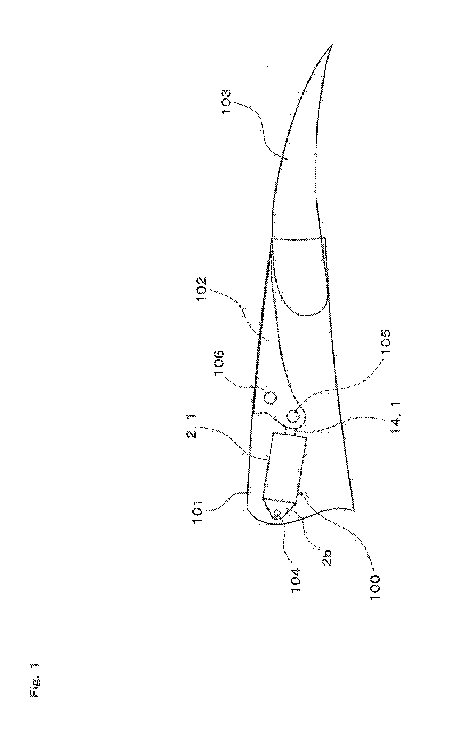
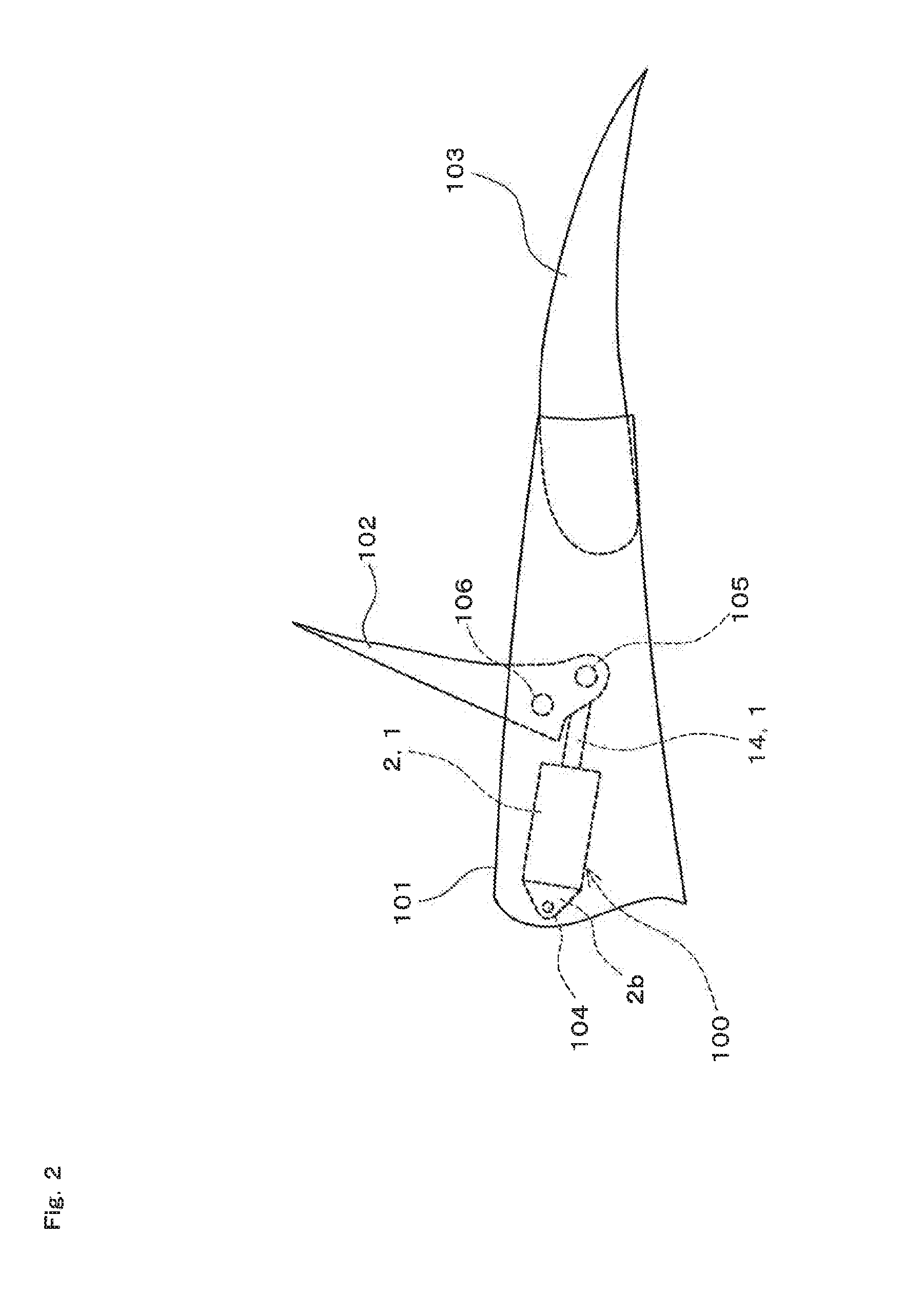
[0039]FIG. 1 is a schematic view showing an exemplary state where an electromechanical actuator 1 according to an embodiment of the present invention is attached to a wing 101 and a moving surface 102 of an aircraft. FIG. 1 omits the main part of the aircraft. FIG. 1 schematically shows a part of...


PUM


Abstract

An electromechanical actuator is provided whose structure is simplified and made small, and with which an output portion can be driven even if a jammed state occurs in a screw mechanism. An electromechanical actuator is configured that includes an electric motor having a first rotor portion and a second rotor portion capable of relative rotation with respect to each other, and a jam relief mechanism having a first conversion portion having a first screw mechanism capable of converting rotational force of the first rotor portion into thrust force and moving an output portion back and forth, a sliding support mechanism which can transmit the rotational force of the first rotor portion to the first conversion portion, and a second conversion portion having a second screw mechanism which moves the output portion back and forth together with the first conversion portion.

Description

CROSS-REFERENCE TO RELATED APPLICATION[0001]This application is based upon and claims the benefit of priority from Japanese patent application No. 2013-210821, the disclosure of which is herein incorporated by reference in its entirety.BACKGROUND OF THE INVENTION[0002]1. Field of the Invention[0003]The present invention relates to an electromechanical actuator that has a screw mechanism, converts rotational driving force which is output by an electric motor into linear driving force, and outputs the converted driving force.[0004]2. Description of the Related Art[0005]Conventionally, an electromechanical actuator having an electric motor and a screw mechanism has been used in various fields such as the field of aircrafts. This electromechanical actuator converts rotational driving force that is output by the electric motor into linear driving force and outputs the converted driving force, using the screw mechanism. The electromechanical actuator drives various kinds of equipment by a...

Claims


Application Information

Patent Timeline
Patent Type & Authority Applications(United States)
IPC IPC(8): H02K7/06F16H25/20H02K16/02
CPCH02K7/06F16H25/205H02K16/02F16H2025/2078H02K2213/06
Inventor UEYAMA, MASAYOSHIHIGUCHI, RYOICHI
Owner NABLESCO CORP
Why Eureka
Try Eureka