Servo data writing device

a data writing and servo technology, applied in the direction of maintaining the head carrier alignment, digital recording, instruments, etc., can solve the problems of uneconomical extra work, high manufacturing cost, and inability of the magnetic disk drive unit to position its own magnetic head

Inactive Publication Date: 2005-06-21
TOSHIBA STORAGE DEVICE CORP
View PDF11 Cites 11 Cited by
  • Summary
  • Abstract
  • Description
  • Claims
  • Application Information

AI Technical Summary

Benefits of technology

[0029]With this basic structure, even if the record starting point and terminating point of the reference clock signals, which are written by the clock head, are not smoothly connected and the duty ratio of the reference clock signals is not partially fixed, the servo data can be correctly written in the magnetic disk because the pattern generating circuit, which generates the servo data, does not use the reference clock signals and signals, which are generated by a PLL circ...

Problems solved by technology

When the servo data are written in the magnetic disk, no servo data have been written in the magnetic disk, so the magnetic disk drive unit cannot position its own magnetic head.
Firstly, the conventional servo data writing device 50 should have the external actuator 58 and the external actuator control circuit 64, which correspond to the magnetic disk drive unit to be attached, as positioning means. And, the clock head 74, the second write-read control circuit 76, the driving mechanism 78 and the first write-read control circuit 68 should be required so as to write the ...

Method used


Image

  • Servo data writing device
  • Servo data writing device
  • Servo data writing device

Examples


first embodiment

[0039]Firstly, the servo data writing device, which has simple inner structure and which effectively uses basic functions of a magnetic disk drive unit, will be explained. Note that, elements described in “BACKGROUND OF THE INVENTION” are assigned the same symbols and detail explanation will be omitted.

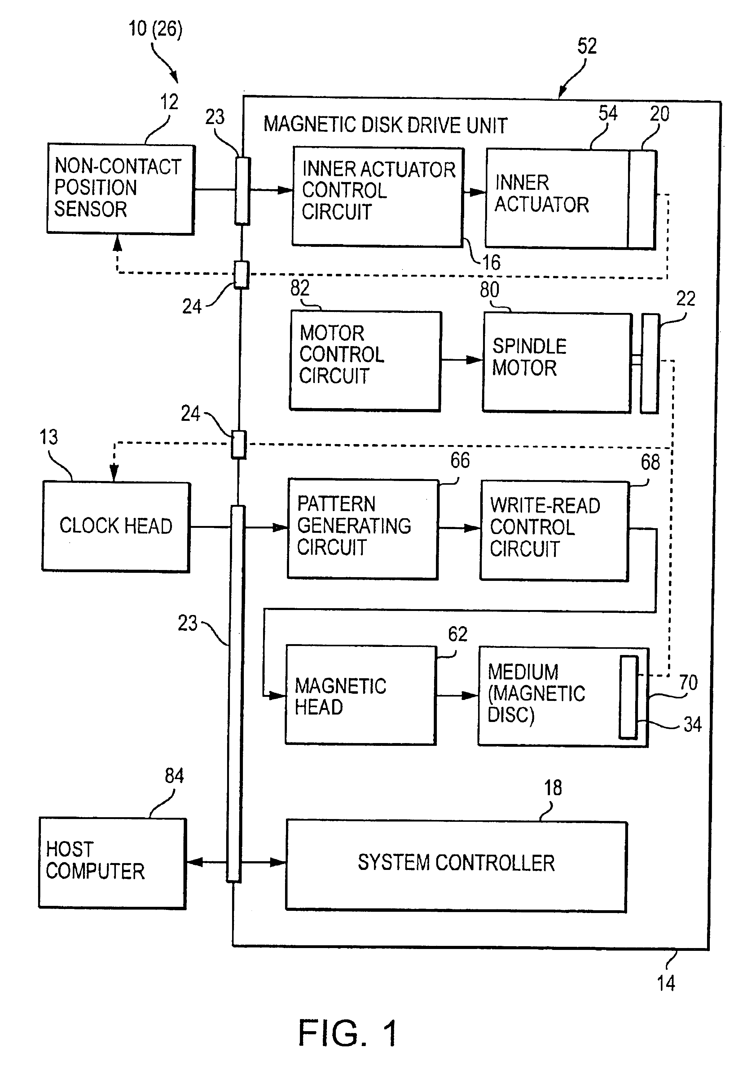
[0040]The servo data writing device 10 of the present embodiment will be explained with reference to FIG. 1.

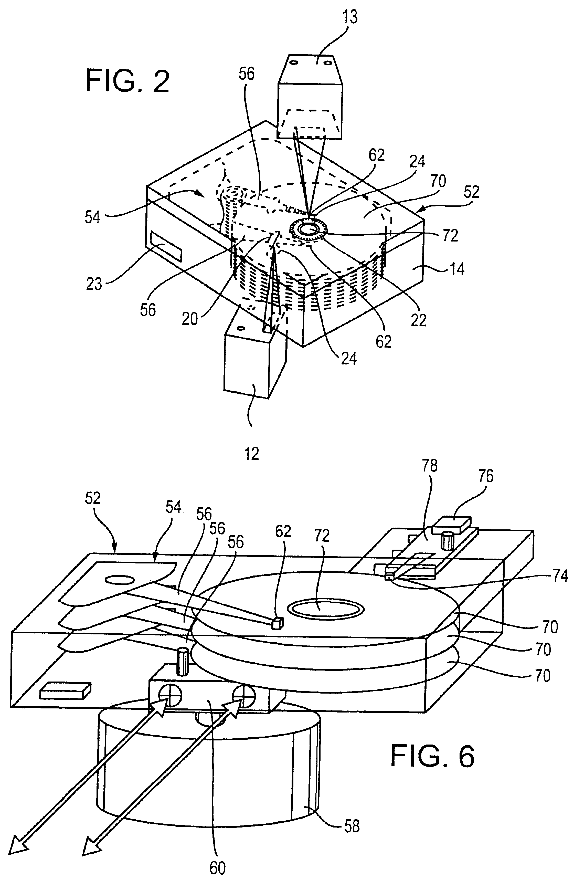
[0041]The servo data writing device 10 comprises: a non-contact position sensor 12 for detecting present positions of arms 56 of an inner actuator 54, which is assembled in a magnetic disk drive unit 52, without contact; a clock head 13 detecting rotation of a spindle 72 or a magnetic disk 70, which is assembled in the magnetic disk drive unit 52, and generating reference clock signals, which are changed on the basis of the rotation of the spindle 72 or the magnetic disk 70; and a host computer 84 capable of controlling the whole servo data writing device 10 and the magnetic dis...

second embodiment

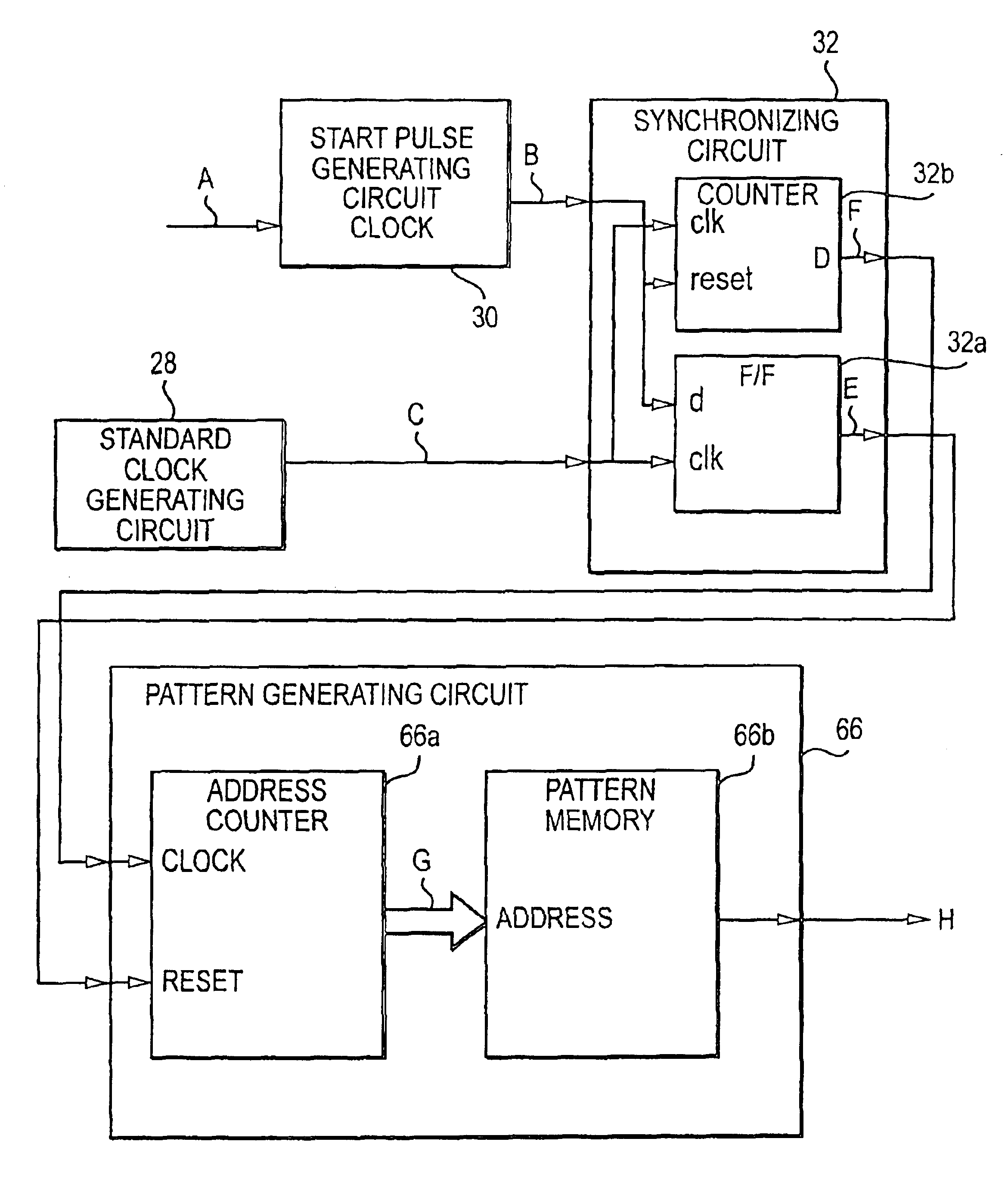
[0076]In Second Embodiment, the reference clock signals, which are generated from the clock head, are not directly used by the pattern generating circuit, which generates the servo data, as clock signals, so that the servo data can be correctly written or recorded even if the duty ratio of the reference clock signals is partially fixed. Note that, the elements described in “BACKGROUND OF THE INVENTION” and the First Embodiment are assigned the same symbols and detail explanation will be omitted.

[0077]Firstly, the structure of a servo data writing device 26 will be explained. The characteristic point of the present embodiment is the pattern generating circuit 66 and peripheral circuits. The basic structure of the servo data writing device 26 may be the same as that of the First Embodiment (see FIG. 1) or that of the conventional device (see FIG. 7).

[0078]In the present embodiment, for example, the servo data writing device 26 has the structure shown in FIG. 7, in which the reference ...


PUM


Abstract

A servo writing device which writes servo data in each sector of each track of a magnetic disk, wherein servo data recorded positions of the tracks are mutually corresponded. The servo writing device includes a clock head for generating reference clock signals and a standard clock generating circuit generating standard clock signals, whose frequency is higher than that of the reference clock signals and which is not synchronized with the reference clock signals. The device further includes a start pulse generating circuit receiving the reference clock signals as clock signals and generating a start pulse corresponding to the servo data recorded position and a synchronizing circuit synchronizing the start pulse with the standard clock signals and generating a synchronizing-start pulse. In addition, the device also includes a pattern generating circuit receiving the standard clock signals as clock signals and generating the servo data synchronizing with the synchronizing-start pulse.

Description

[0001]This is a divisional of application Ser. No. 09 / 357,683, filed Jul. 20, 1999 now abandoned.BACKGROUND OF THE INVENTION[0002]The present invention relates to a servo data writing device which writes servo data for positioning a magnetic head for writing and reading data on a magnetic disk of a magnetic disk drive unit.[0003]Magnetic disks are assembled in a magnetic disk drive unit. A plurality of tracks are coaxially formed in each magnetic disk. Servo data are magnetically written in each sector of each track. The servo data are used to position magnetic heads in object tracks.[0004]When the servo data are written in the magnetic disk, no servo data have been written in the magnetic disk, so the magnetic disk drive unit cannot position its own magnetic head.[0005]For example, the magnet disk drive unit is assembled by the steps of: assembling a motor for rotating a spindle; attaching magnetic disks to the spindle; assembling an inner actuator, which has arms for holding the m...

Claims


Application Information

Patent Timeline
IPC IPC(8): G11B5/596G11B21/10
CPCG11B5/59633G11B5/59638
Inventor FUKUSHI, MASANORIISHIJIMA, MASARU
Owner TOSHIBA STORAGE DEVICE CORP
Why Eureka
Try Eureka