Pattern writing apparatus and block number determining method

a pattern writing and block number technology, applied in the field of pattern writing apparatus, can solve the problems of limitation in the speed of pattern writing, inability to obtain ideal light amount, etc., and achieve the effect of maximizing scan speed, accurately writing a pattern on the photosensitive material, and stably writing a pattern at high speed

Active Publication Date: 2007-09-11
DAINIPPON SCREEN MTG CO LTD
View PDF27 Cites 8 Cited by
  • Summary
  • Abstract
  • Description
  • Claims
  • Application Information

AI Technical Summary

Benefits of technology

[0008]According to the present invention, it is possible to write a pattern on the photosensitive material stably at high speed.
[0009]According to a preferred embodiment of the present invention, the block number determining part obtains a first upper limit value of a scan speed on the basis of the writing pitch and required time function for inputting the writing signal where the number of modulation blocks to be used is a parameter, and a second upper limit value of a scan speed on the basis of the maximum light amount function of light applied on a photosensitive material where the number of the modulation blocks to be used is a parameter, a substantial width in a direction perpendicular to the scanning direction of irradiation blocks corresponding to the modulation blocks to be used, and sensitivity of the photosensitive material, and the block number determining part determines the number of the modulation blocks to be used where smaller one of the first upper limit value and the second upper limit value is maximum as the operating block number. This allows to determine the number of modulation blocks used for actual pattern writing appropriately by computation.
[0010]More preferably, the pattern writing apparatus further comprises a light amount sensor for detecting an amount of light applied on a photosensitive material from the light source part through the spatial light modulator, and in the apparatus, the block number determining part obtains the maximum light amount on the basis of the amount of light. It is thereby possible to write a pattern on the photosensitive material accurately.
[0011]According to another preferred embodiment of the present invention, the pattern writing apparatus further comprises a memory for storing a reference table representing a relationship between the number of modulation blocks where a scan speed can be maximized and sensitivity of a photosensitive material, and in the apparatus, the block number determining part determines the operating block number by referring to the reference table and sensitivity of a photosensitive material to be written. This makes it possible to determine the number of modulation blocks used for actual pattern writing easily.

Problems solved by technology

When light from a light source such as a discharge lamp or the like is directed on a photosensitive material through an optical system, if it is intended to increase an amount of applied light per unit area on the photosensitive material by reducing the size of a region where the light is emitted, an ideal light amount cannot be obtained due to the technical limitation of convergence of light in the optical system in some cases.
Thus, if only a few blocks are used in writing a pattern on the photosensitive material with low sensitivity (i.e., light amount required for exposure is large) in the method of Document 1, a scan speed of the irradiation region group on the photosensitive material has to be set low from the viewpoint of application of necessary light amount on the photosensitive material, and this causes limitation in the speeding up of pattern writing.

Method used


Image

  • Pattern writing apparatus and block number determining method
  • Pattern writing apparatus and block number determining method
  • Pattern writing apparatus and block number determining method

Examples


Embodiment Construction

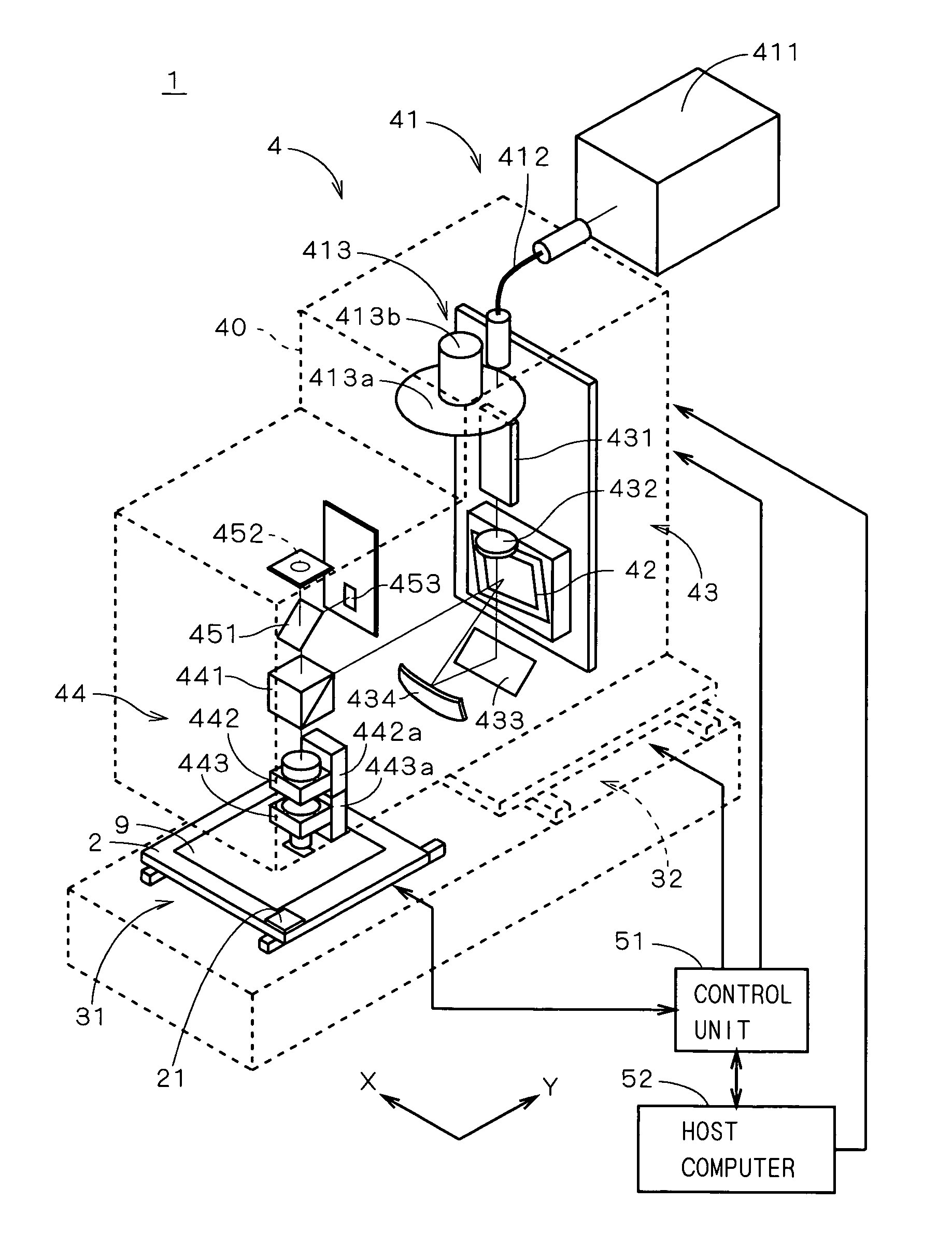
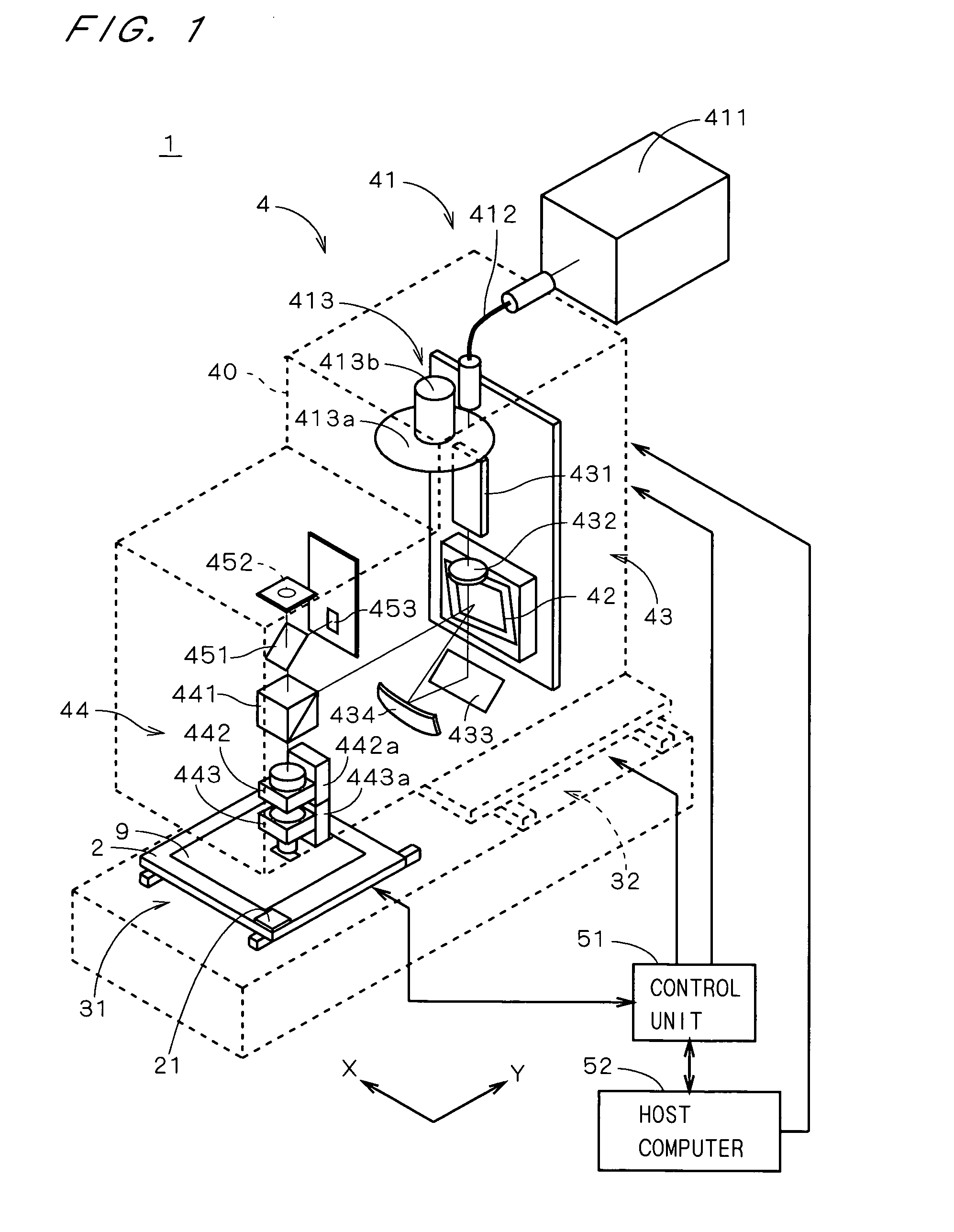
[0033]FIG. 1 is a diagram illustrating a structure of a pattern writing apparatus 1 according to a first preferred embodiment of the present invention. In FIG. 1, part of the apparatus is shown by dashed lines for illustration of the internal structure of the apparatus. The pattern writing apparatus 1 comprises a stage 2 holding a substrate 9 on which a photoresist film is formed, a stage moving mechanism 31 for moving the stage 2 in the Y direction in FIG. 1, a light irradiating part 4 for emitting light beams to the substrate 9, a light amount sensor 21 provided on the stage 2, detecting an amount of light beams emitted from the light irradiating part 4, a head moving mechanism 32 for moving a head 40 of the light irradiating part 4 in the X direction in FIG. 1, a control unit 51 connected to the light irradiating part 4, the light amount sensor 21, the stage moving mechanism 31, and the head moving mechanism 32, and a host computer 52 connected to the control unit 51, constituted...


PUM


Abstract

A pattern writing apparatus comprises a DMD for spatially modulating light from a light source and directing modulated light beams to a plurality of irradiation regions, respectively, which are arranged on a substrate two-dimensionally. A pattern is written by controlling the DMD while scanning the plurality of irradiation regions. The plurality of irradiation regions form a plurality of irradiation blocks arranged in a column direction, in each of which irradiation regions are arranged in a row direction. In DMD, writing signal is sequentially inputted to mirror blocks to be used out of a plurality of mirror blocks corresponding to the plurality of irradiation blocks, respectively. When writing a pattern, an operation part determines the number of mirror blocks to be used where scan speed can be maximized, in consideration of required time for input of the writing signal to the DMD and light amount applied on the substrate.

Description

BACKGROUND OF THE INVENTION[0001]1. Field of the Invention[0002]The present invention relates to a pattern writing apparatus with a spatial light modulator and a block number determining method for determining the number of modulation blocks of a spatial light modulator used for actual pattern writing in a pattern writing apparatus.[0003]2. Description of the Background Art[0004]Conventionally, a technique for writing a pattern on a photosensitive material by using a spatial light modulator has been suggested. As such a technique, for example, Japanese Patent Application Laid Open Gazette No. 2003-332221 (Document 1) discloses a technique where an irradiation region group onto which a DMD (Digital Micromirror Device) is projected is scanned over a photosensitive material in a scanning direction which is tilted relative to a direction of arrangement of the irradiation region group, whereby writing a pattern on a writing cell group which is set on the photosensitive material at higher...

Claims


Application Information

Patent Timeline
Patent Type & Authority Patents(United States)
IPC IPC(8): G03B27/54G03B27/32
CPCG02B26/0833G03F7/70291G03F7/70508G03F7/70558G03F7/2057
Inventor SHIROTA, HIROYUKIHISAOKA, KATSUYUKI
Owner DAINIPPON SCREEN MTG CO LTD
Why Eureka
Try Eureka