Device for hanging an object on a wall

a technology for hanging objects and objects, applied in the direction of building components, structural elements, building scaffolds, etc., can solve the problems of inconvenient use, large device weight, cumbersome connection to picture frames, etc., and achieve the effect of facilitating the insertion of fasteners and facilitating horizontal levelling of objects

Active Publication Date: 2012-06-21
SCHNEIDER TIMOTHY WAYNE
View PDF23 Cites 33 Cited by
  • Summary
  • Abstract
  • Description
  • Claims
  • Application Information

AI Technical Summary

Benefits of technology

[0006]There is accordingly provided a device for hanging an object on a wall. The device includes a wall mount for fastening to the wall. The device includes an object mount for fastening to the object. A first one of the mounts has a first bracket portion and a second bracket portion each being u-shaped and configured to receive at least part of a second one of the mounts. The bracket portions have a space between the first bracket portion and the second bracket portion. The second one of the mounts has a projection disposable in the space between the bracket portions. The bracket portions enable horizontal positioning of the object mount relative to the wall mount to be adjustable. The projection is configured to interact with the bracket portions and limit horizontal movement of the object mount relative to the wall mount to within a set range spanning the space from a first position, where the projection abuts the first bracket portion, to a second position where the projection abuts the second bracket portion.
[0007]There is also provided a device for hanging an object on a wall. The object has a horizontal edge. The wall has a wall stud. The device includes a wall mount for fastening to the wall stud. The wall mount has a plurality of apertures configured to align with the wall stud, the apertures allowing for height adjustability and enabling fasteners to pass therethrough for engaging with the wall stud. The device includes an object mount for fastening to the object. A first one of the mounts has at least one bracket portion configured to receive at least part of a second one of the mounts. At least part of the bracket portion is u-shaped in cross-section. The object mount has a peripheral edge. The object mount has a plurality of apertures extending parallel to and spaced-apart from the peripheral edge. The object mount has a pair of spaced-apart positioning tabs disposed along and extending outwards from the peripheral edge of the object mount. The positioning tabs are configured to abut against the horizontal edge of the object. The positioning tabs thus act to facilitate horizontal levelling of the object relative to the object mount and facilitate insertion of fasteners through the apertures of the object mount and into the object. The object mount is fastened to the object thereby.
[0008]There is further provided a device for hanging an object on a wall. The device includes a wall mount for fastening to the wall. The device includes an object mount for fastening to the object. A first one of the mounts has a first bracket portion and a second bracket portion each configured to receive at least part of a second one of the mounts. At least part of each of the bracket portions is u-shaped in cross-section. Each of the bracket portions has an elongated slot. The slots have a first end and a second end opposite thereof. The first ends of the slots face each other. The second one of the mounts has a projection shaped to at least partially extend through the slots. The bracket portions enable horizontal positioning of the object mount relative to the wall mount to be adjustable. The projection is configured to interact with the bracket portions and limit horizontal movement of the object mount relative to the wall mount to within a set range spanning the space from a first position, where the projection abuts a part of the first bracket portion adjacent to the second end of its slot, to a second position where the projection abuts a part of the second bracket portion adjacent to the second end of its slot.

Problems solved by technology

However relying on the position on the wall stud may result in an inconvenience to the user, because the location of the wall stud may not correspond with a desired position of the picture frame relative to the rest of the wall and room.
However, some of these devices may require numerous parts and thus may be relatively expensive to manufacture.
Also, some of these devices may be bulky and cumbersome to assemble and connect to picture frames.
Moreover, some such devices may render the picture frame susceptible to slidably dislodging off the wall and falling to the floor, thereby increasing the risk that the picture may become damaged.

Method used


Image

  • Device for hanging an object on a wall
  • Device for hanging an object on a wall
  • Device for hanging an object on a wall

Examples


Embodiment Construction

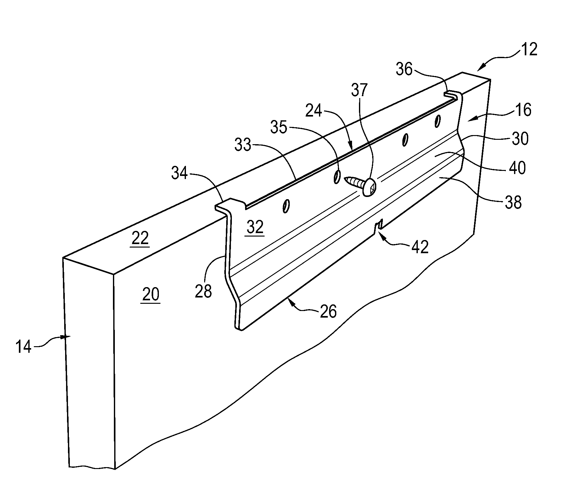
[0025]Referring to the drawings and FIGS. 1, 5 and 7, there is provided a device 12 for hanging an object, in this example a picture frame 14, onto a wall 15, shown in FIG. 8. As shown in FIG. 1, the picture frame 14 has a back side 20 and a peripheral edge in this example a top horizontal edge 22.

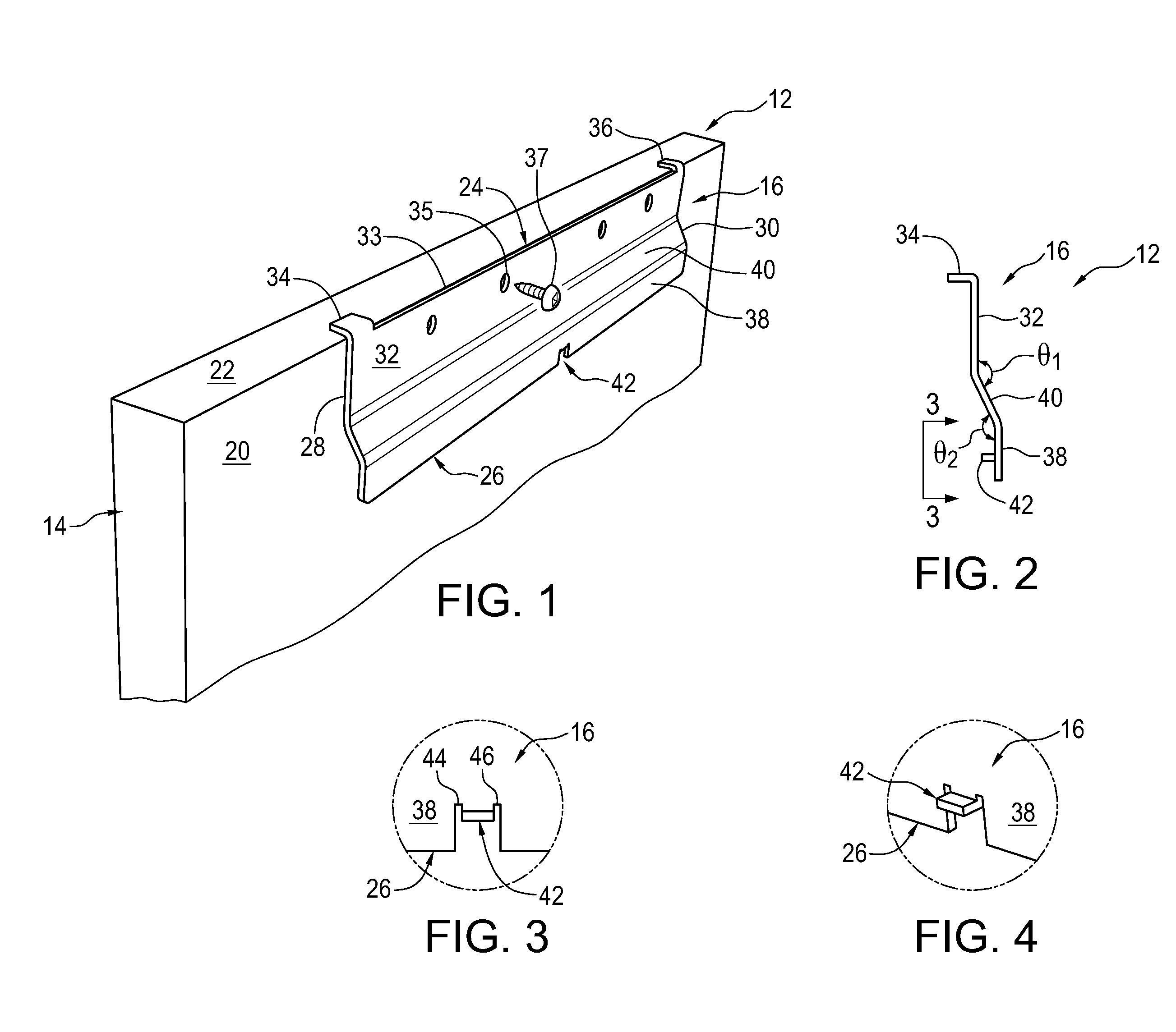
[0026]The device 12 includes an object mount 16 as best shown in FIGS. 1 to 4. The object mount 16 in this example is made of sheet metal cut and bent into the desired shape. The object mount 16 has a top 24, a bottom 26 opposite thereof and a pair of opposed sides 28 and 30. The object mount 16 has an elongate mounting strip 32 adjacent the top 24. The strip is generally rectangular in shape in this example and extends from side 28 to side 30. The mounting strip 32 is configured to abut with and extend along the back side 20 of the picture frame 14. The object mount 16 includes a plurality of apertures 35 extending through the mounting strip 32. The apertures 35 receive fasteners such as ...


PUM


Abstract

There is provided a device for hanging an object on a wall. The device includes a wall mount and an object mount. One mount has a first bracket portion and a second bracket portion each being u-shaped and configured to receive the other mount. The bracket portions have a space between the bracket portions. The other mount has a projection disposable in the space between the bracket portions. The projection also acts as a safety tab. The bracket portions enable horizontal positioning of the object mount relative to the wall mount to be adjustable. The projection is configured to interact with the bracket portions and limit horizontal movement of the object mount relative to the wall mount to within a set range spanning the space from a first position, where the projection abuts the first bracket portion, to a second position where the projection abuts the second bracket portion.

Description

FIELD OF THE INVENTION[0001]The present invention relates to a device for hanging an object on a wall, and in particular, hanging a frame picture, mirror or the like, onto a wall.DESCRIPTION OF THE RELATED ART[0002]It is known to provide a device for hanging an object, such as a picture frame, on a wall where the device comprises an elongate u-shaped bracket that engages a corresponding elongate angled bracket with apertures that can align with studs. However relying on the position on the wall stud may result in an inconvenience to the user, because the location of the wall stud may not correspond with a desired position of the picture frame relative to the rest of the wall and room.[0003]Some devices of the known prior art allow for horizontal adjustability of the picture frame. However, some of these devices may require numerous parts and thus may be relatively expensive to manufacture. Also, some of these devices may be bulky and cumbersome to assemble and connect to picture fra...

Claims


Application Information

Patent Timeline
Patent Type & Authority Applications(United States)
IPC IPC(8): F16M13/02
CPCF16M13/02A47G1/1606A47F7/14
Inventor SCHNEIDER, TIMOTHY WAYNE
Owner SCHNEIDER TIMOTHY WAYNE
Why Eureka
Try Eureka