

Method and Apparatus for Header Compression in Network Relay Scenario
- Summary
- Abstract
- Description
- Claims
- Application Information
AI Technical Summary
Benefits of technology
Problems solved by technology
Method used
Image

Examples
Embodiment Construction
[0056]To make the objectives, the technical solutions, and the advantages of the embodiments of the present application clearer, the embodiments of the present application are described in detail below with reference to the accompanying drawings.
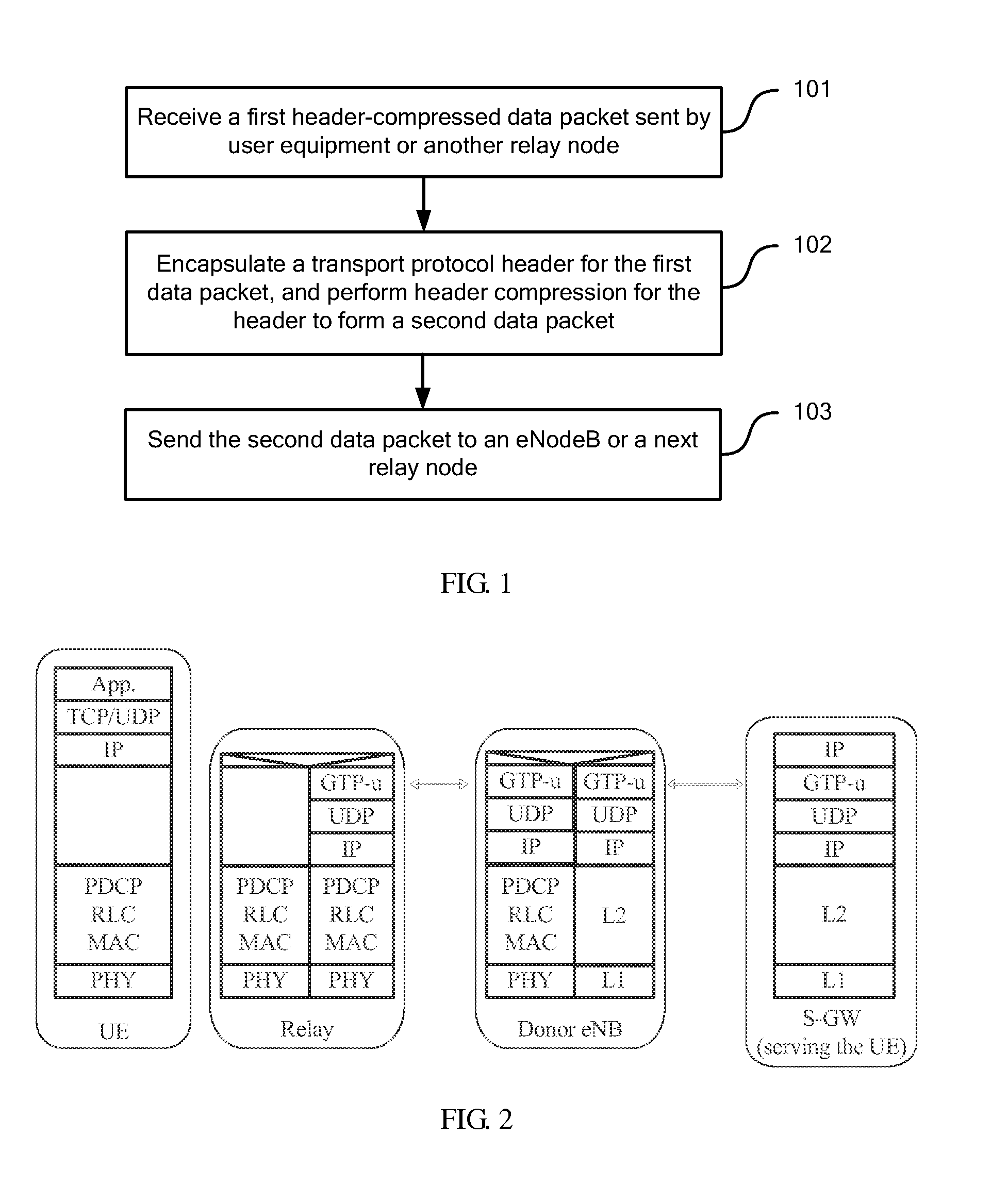
[0057]FIG. 1 is a flow chart of a method for header compression in a network relay scenario according to an embodiment of the present invention, which includes the following:
[0058]101. Receive a first header-compressed data packet sent by user equipment or another relay node.
[0059]102. Encapsulate a transport protocol header for the first data packet, and perform header compression for the header to form a second data packet.
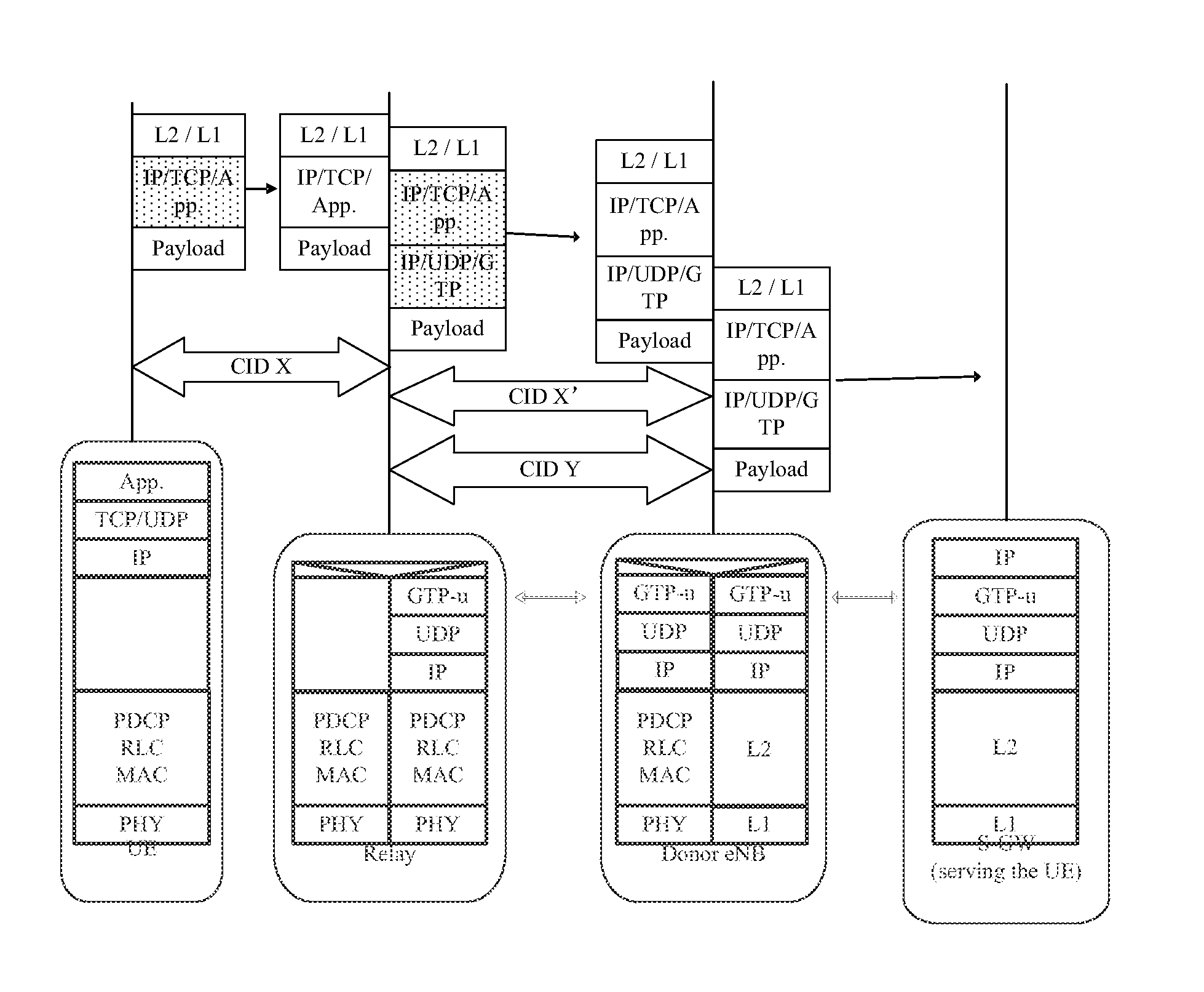
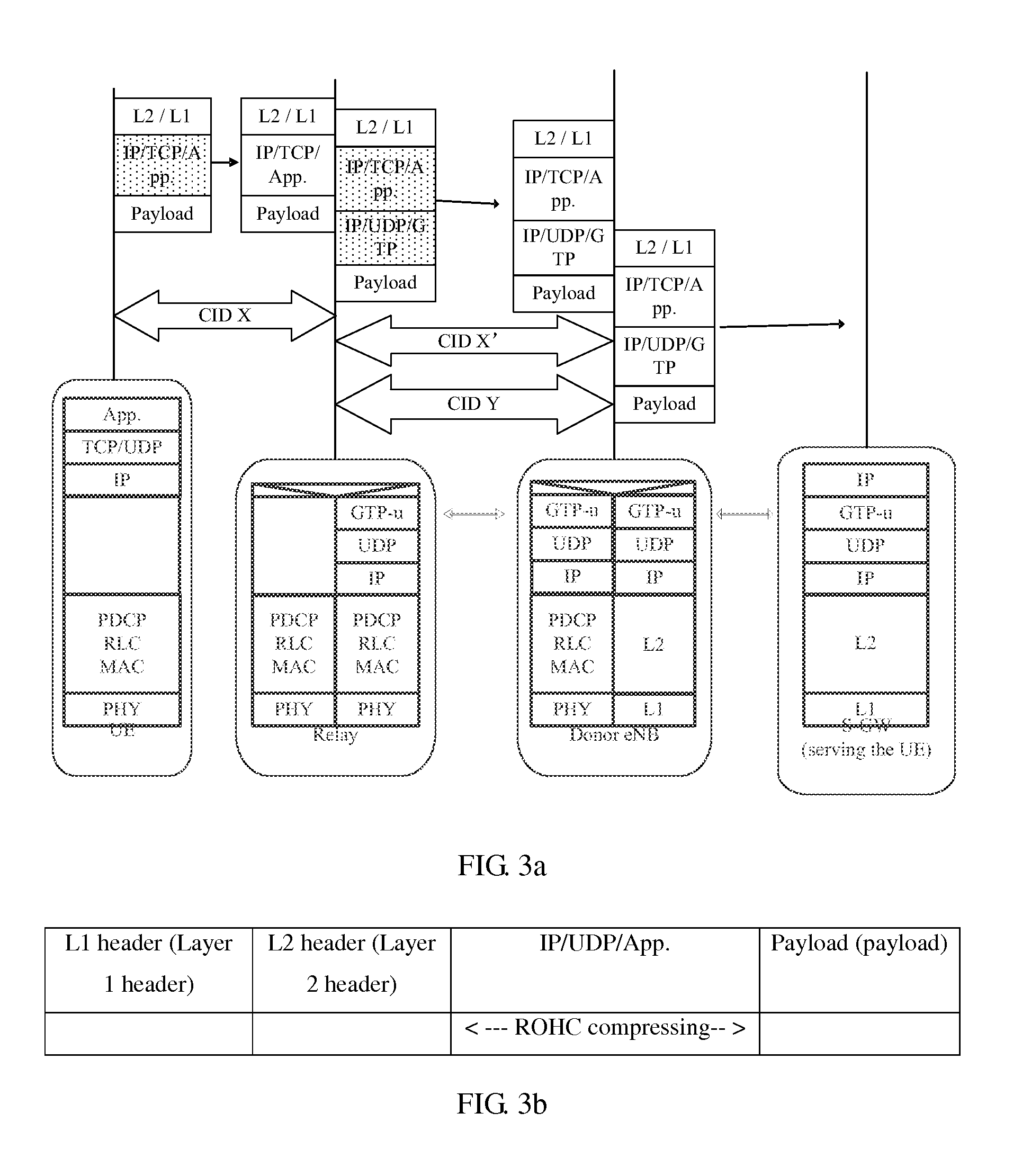
[0060]The transport protocol specifically includes: a tunneling protocol and a transport protocol for the tunneling protocol. The tunneling protocol includes: GTP-U (GPRS Tunneling Protocol-User plane, general packet radio service tunneling protocol-user plane). An IP / UDP (user datagram protocol) protocol header is encap...
PUM
 Abstract
Description
Claims
Application Information