Method and apparatus for multi-beam beamformer based on real-time calculation of time delay and pipeline design

Inactive Publication Date: 2011-09-29
SHENZHEN LANDWIND IND
View PDF5 Cites 26 Cited by
  • Summary
  • Abstract
  • Description
  • Claims
  • Application Information

AI Technical Summary

Benefits of technology

[0016]It is an objective of the present invention to provide a method and an apparatus for calculating delay parameters in real time, which is adapted to be used in different probes of different shape and reduces the occupation of hardware resource. Considering different types of probe, the present invention provides a universal delay calculation apparatus. The apparatus separates the parameters that should be calculated in real time from the parameters that does not require real-time calculation, and separates the parameters related to the beam sequencing number and the parameters that are independent of the beam sequencing number, and provides a real-time delay calculation unit that is adapted to different types of probe by means of simple switching. The calculation unit utilizes the pipeline design, the delay parameters of M number of beams are calculated in the calculation unit in pipeline manner, and then the memory of the same echo signal da

Problems solved by technology

However, many of them are always at the cost of reducing frame rate.
For fast imaging being required for observing moving object in clinical practice, the great reduction of frame rate will limit its use in cardiopathy diognosis.
Comparing with the normal way of scanning, the multi-beam beamforming technique may generate M number of scan lines (normally, M is in a range of 2 to 16) simultaneously during one transmitting process, and thus the frame rate is improved by M times. However, it is a difficult technical problem to implement the multi-beam technique.
In this way, a huge quantity memory are required to implement multibeam beamformer.
Meanwhile, the demand with respect to the FPGA resource is increased by several times such that it is impossible to be realized.
However, for the quantity of focus that realizes the dynamic focusing may reach up to one thousand to even several thousands, the great memory capacity is still needed.
However, this patent does not disclose how to generate time delay parameters.
However, for the reason that the element position coordinates and the focus position coordinates should be stored simultaneously, a large storage amount is also needed, and if each focus position coordinate is calculated, the calculation would be too complicated and

Method used


Image

  • Method and apparatus for multi-beam beamformer based on real-time calculation of time delay and pipeline design
  • Method and apparatus for multi-beam beamformer based on real-time calculation of time delay and pipeline design
  • Method and apparatus for multi-beam beamformer based on real-time calculation of time delay and pipeline design

Examples


Example

[0064]Many aspects of the present invention will be described in more detail in the following embodiments, with the accompanying drawings.

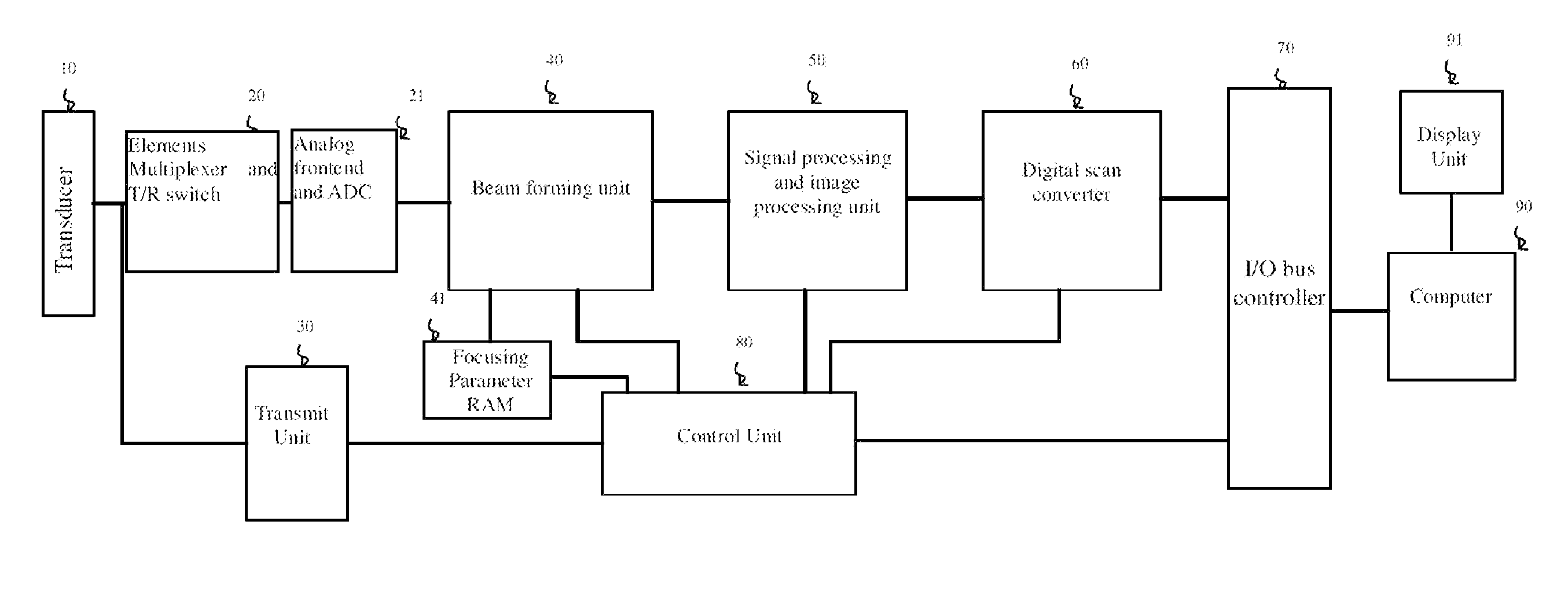
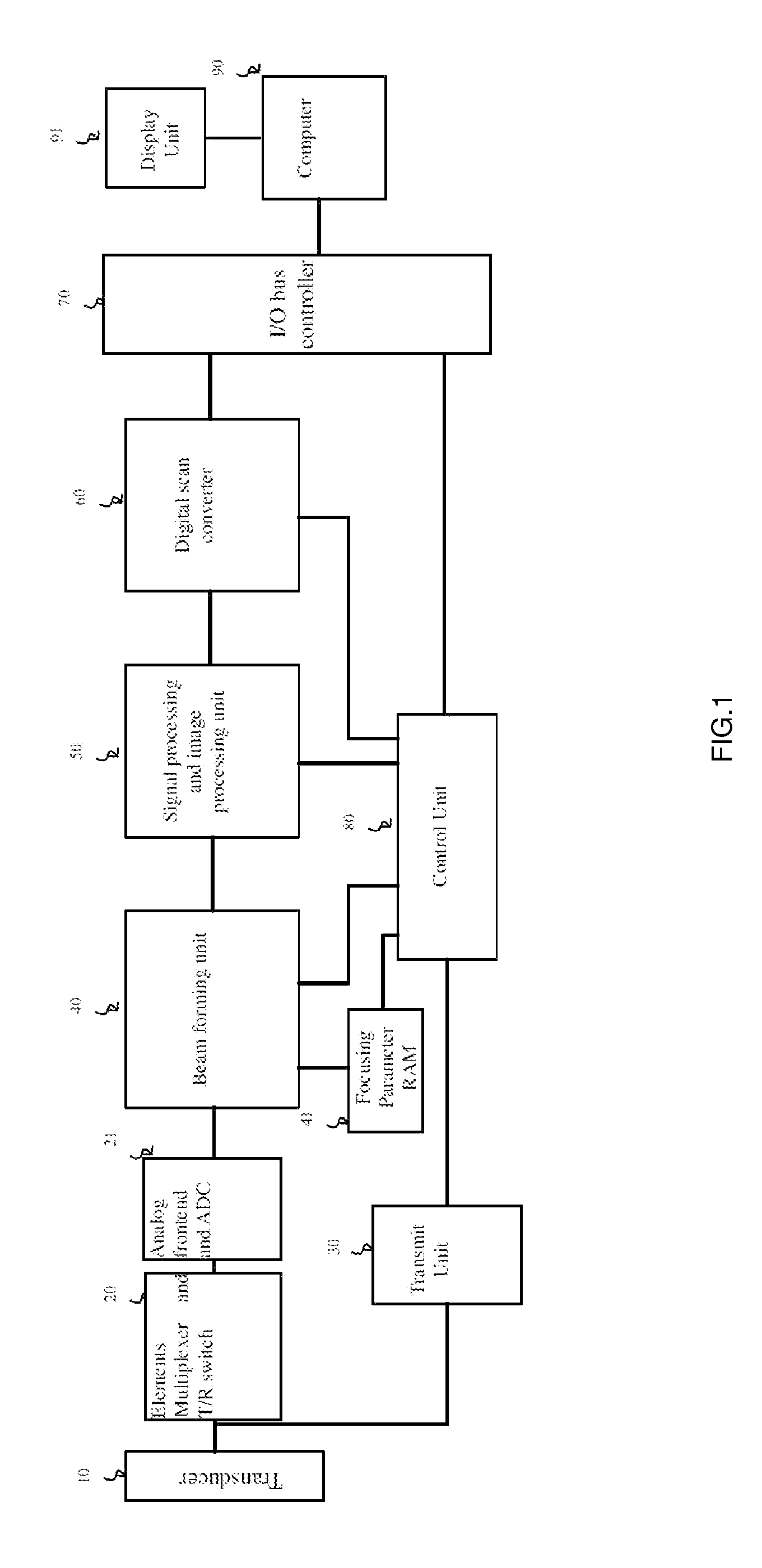
[0065]FIGS. 4 and 5 give examples of beamforming solution. In FIG. 4, the echo signal from the receive / transmit switch is transmitted to the analog frontend 200 and then the analog-to-digital converter 300 to be converted into digital signal. Then, the digital signal is transmitted to the DC cancellation unit 400 to filter the low frequency component and then be written into the dual port RAM 501 linearly under control by the control unit 500; the most important difference lies in that, the delay parameter calculation unit 600 is added in FIG. 4. The delay calculation unit calculates the delay amount in real time according to the element parameters corresponding to the current channel and the focus position parameter. As for the beamforming of M number of beams, the delay parameters of the M number of beams are calculated by the delay parameter ca...


PUM


Abstract

A multi-beamforming method based on real-time calculation of delay parameter and pipeline technique and an apparatus there of are disclosed. The system separates the parameters that should be calculated in real time from the parameters that does not require real-time calculation, and separates the parameters related to the beam sequencing number and the parameters that are independent of the beam sequencing number, and provides a real-time delay calculation unit that is adapted to different types of probe by means of simple switching. The calculation unit utilizes the pipeline design, the delay parameters of M number of beams are calculated in the calculation unit in pipeline manner, and then the memory of the same channel echo data is read, so that the delay of the beams is realized. The consumption of the FPGA resource is greatly reduced. The present invention enables high delay precision through direct calculation. In order to reduce the occupation of the hardware resource, the present invention uses the pipeline design to allow M number of beams to share the delay parameter calculation unit. The occupation of the hardware resource is greatly reduced accordingly.

Description

BACKGROUND OF THE INVENTION[0001]This invention relates to an ultrasound imaging system using linear probes, convex probes and phased array probes, in particular to a multi-beam beamforming system based on real-time calculation of time delay and pipeline design.[0002]The quality of ultrasound imaging has been greatly improved in recent decades, owing to many advanced techniques in radar and the digital signal processing and image processing technique being used. However, many of them are always at the cost of reducing frame rate. For example, in the spatial compound imaging, it is necessary to synthesize images of multi-frame scanned from different angles to obtain the final image; phase-inversion tissue harmonic technique requires that two frame images obtained from different transmitting pulse polarity are superposed to obtain the tissue harmonic image; and synthetic aperture focusing technique requires the superposition of multi-frame images to realize the point-by-point focusing...

Claims


Application Information

Patent Timeline
IPC IPC(8): A61B8/14
CPCA61B8/14G10K11/346G01S15/8909G01S7/52095
Inventor MENG, GUOHAI
Owner SHENZHEN LANDWIND IND
Why Eureka
Try Eureka