
Apparatus and method for estimating time stamp

a technology of time stamp and apparatus, applied in the direction of time-division multiplex, electrical apparatus, multiplex communication, etc., can solve the problems of difficult and costly design of such complex clock system, and the ntp may not be suitable for use in the field of application

Active Publication Date: 2012-06-21
ELECTRONICS & TELECOMM RES INST
View PDF6 Cites 42 Cited by
  • Summary
  • Abstract
  • Description
  • Claims
  • Application Information

AI Technical Summary

Benefits of technology

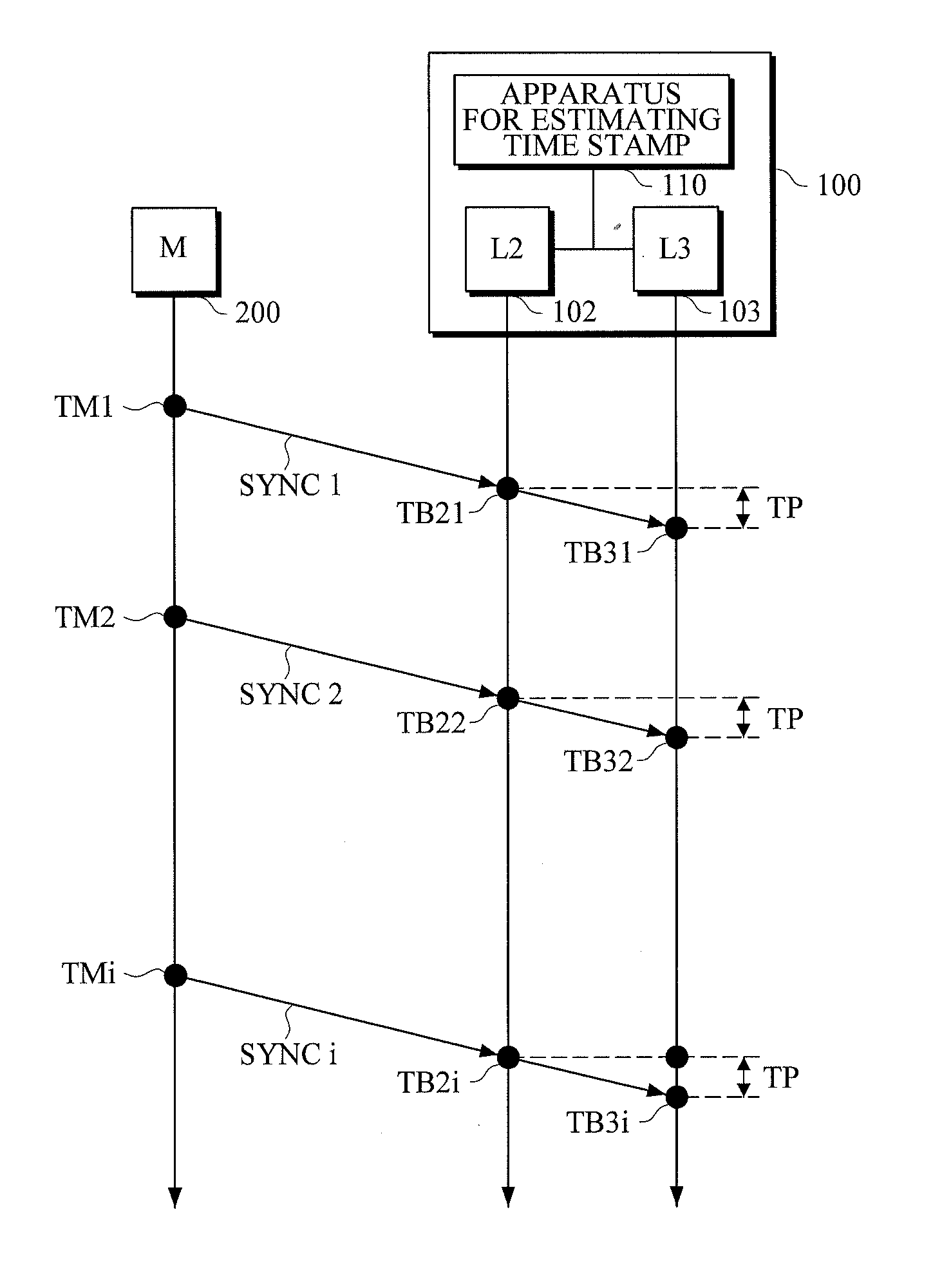
[0017]In another general aspect, there is provided a method of estimating a time stamp for synchronization in time with a master, the method including: extracting a difference between a second time stamp value, which is obtained by adjusting a first time stamp value that is measured at a time of arrival of a synchronization message transmitted by the master at a Layer 3 to be synchronized in frequency with a clock of the master, and a third time stamp value,

Problems solved by technology

However, the design of such complicated clock systems is difficult and costly.
However, NTP may not be suitable for use in fields of application where precise time synchronization is required, for example, in the field of multimedia streaming services for packet switching networks, due to its precision limitations.

Method used


Image

  • Apparatus and method for estimating time stamp
  • Apparatus and method for estimating time stamp
  • Apparatus and method for estimating time stamp

Examples


Embodiment Construction

[0028]The following description is provided to assist the reader in gaining a comprehensive understanding of the methods, apparatuses, and / or systems described herein. Accordingly, various changes, modifications, and equivalents of the methods, apparatuses, and / or systems described herein may be suggested to those of ordinary skill in the art. Also, descriptions of well-known functions and constructions may be omitted for increased clarity and conciseness.

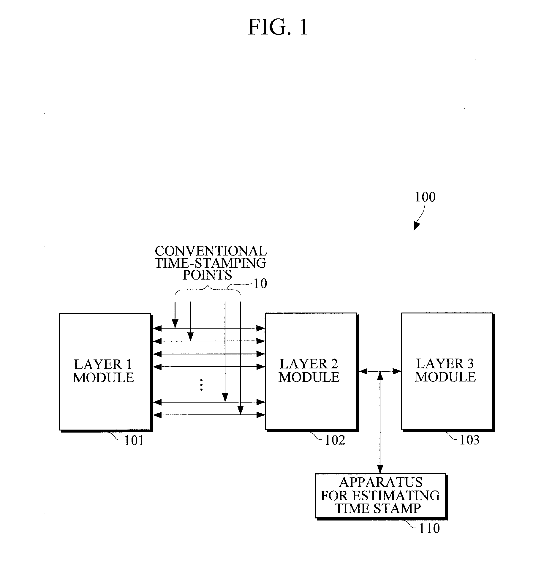
[0029]FIG. 1 illustrates an example of a virtual time-stamping apparatus that applies a time synchronization protocol in a packet network.

[0030]Referring to FIG. 1, virtual time-stamping apparatus 100 includes a Layer 1 module 101, a Layer 2 module 102, a Layer 3 module 103, and an apparatus 110 for estimating a time stamp. For example, the virtual time-stamping apparatus 100 may be implemented as a slave device or a bridge device that is to be synchronized with a master device (not shown).

[0031]The apparatus 110 may measure a time...


PUM


Abstract

An apparatus includes a difference extraction unit to extract a difference between a second time stamp value, which is obtained by adjusting a first time stamp value that is measured at a time of arrival of a synchronization message transmitted by the master at a Layer 3 to be synchronized in frequency with a clock of the master, and a third time stamp value, which is measured at a time of departure of the synchronization message from the master; a minimum filter to select a minimum from one or more difference values extracted by the difference extraction unit; and a delay variation calculation unit to estimate a time of arrival of a current synchronization message at the Layer 3 based on the selected minimum and calculate a delay variation.

Description

CROSS-REFERENCE TO RELATED APPLICATION(S)[0001]This application claims the benefit under 35 U.S.C. §119(a) of Korean Patent Application No. 10-2010-0130271, filed on Dec. 17, 2010, in the Korean Intellectual[0002]Property Office, the entire disclosure of which is incorporated herein by reference for all purposes.BACKGROUND[0003]1. Field[0004]The following description relates to a technique for measuring a virtual time stamp value, and more particularly, to an apparatus and method for precisely estimating a virtual time stamp value based on a time stamp value that is measured in a network system.[0005]2. Description of the Related Art[0006]Synchronous transmission systems such as time division multiplexers (TDMs), synchronous optical network (SONET) / synchronous digital hierarchy (SDH) systems use various clock systems to transmit synchronous data in metro- or wide area network (WAN) areas. However, the design of such complicated clock systems is difficult and costly.[0007]On the othe...

Claims


Application Information

Patent Timeline
IPC IPC(8): H04J3/06
CPCH04J3/0697H04J3/0658H04J3/0638H04J3/0667
Inventor LEE, SEUNG-WOOLEE, BHUM-CHEOLLEE, JUNG-HEE
Owner ELECTRONICS & TELECOMM RES INST
Learn More