PWM controller with dual-edge modulation using dual ramps

Active Publication Date: 2007-01-18
INTERSIL INC
View PDF1 Cites 116 Cited by
  • Summary
  • Abstract
  • Description
  • Claims
  • Application Information

AI Technical Summary

Problems solved by technology

A leading-edge modulation scheme is good for the load-adding transient event but not always responsive to a load-releasing transient, while a trailing-edge modulation scheme is good for the load-releasing transient event but not always responsive to a load-adding transient event.

Method used


Image

  • PWM controller with dual-edge modulation using dual ramps
  • PWM controller with dual-edge modulation using dual ramps
  • PWM controller with dual-edge modulation using dual ramps

Examples


Embodiment Construction

[0033] The following description is presented to enable one of ordinary skill in the art to make and use the present invention as provided within the context of a particular application and its requirements. Various modifications to the preferred embodiment will, however, be apparent to one skilled in the art, and the general principles defined herein may be applied to other embodiments. Therefore, the present invention is not intended to be limited to the particular embodiments shown and described herein, but is to be accorded the widest scope consistent with the principles and novel features herein disclosed.

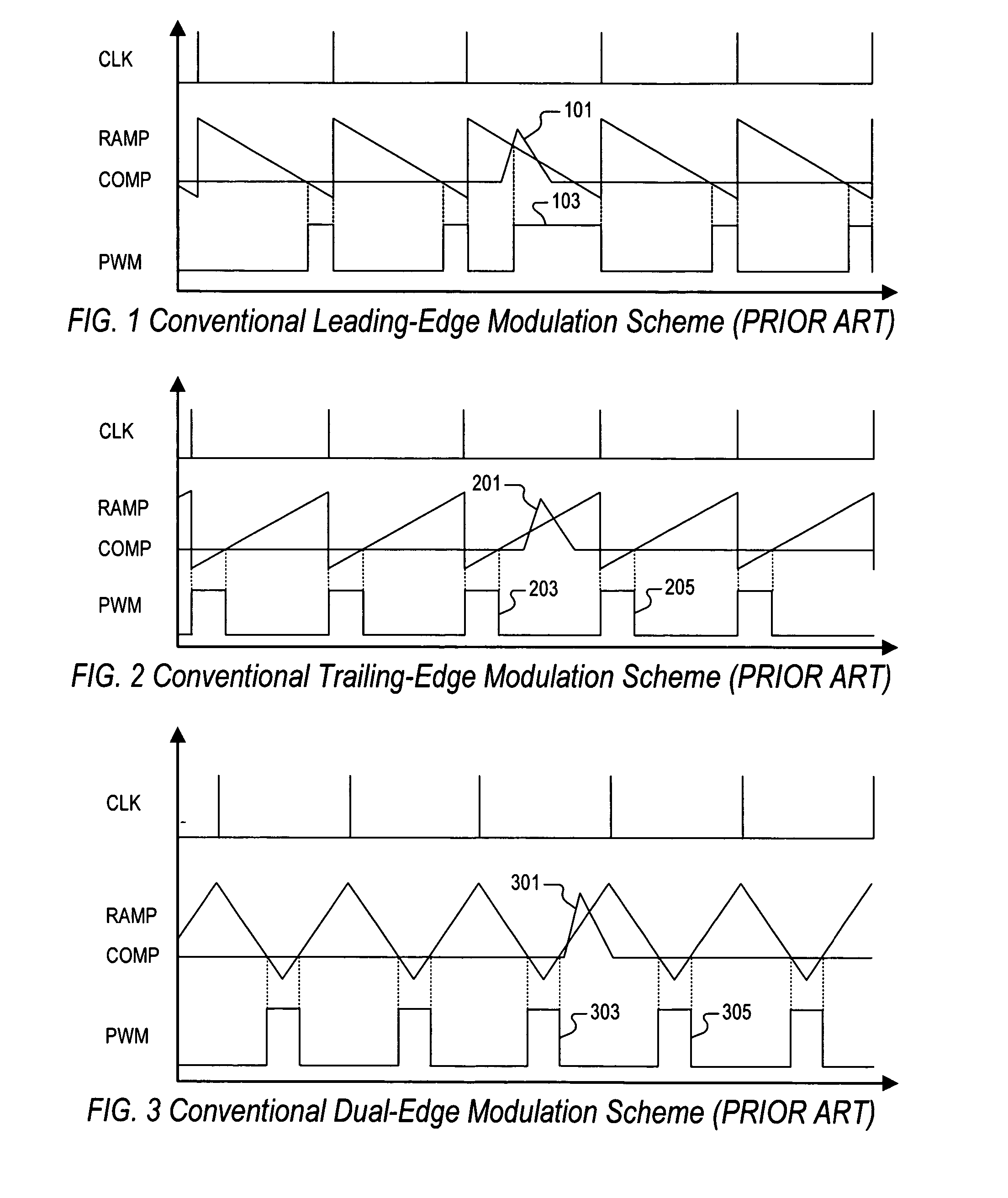
[0034]FIG. 1 is a series of timing diagrams illustrating a conventional leading-edge modulation scheme. Clock (CLK) pulses are shown at the top, a sawtooth waveform signal RAMP and a compensation signal COMP are shown together in the middle and superimposed indicating their relative values, and a resulting pulse width modulation (PWM) signal is shown at bottom. The RAMP signa...


PUM


Abstract

A dual-edge modulation controller including first and second ramp circuits, first and second comparators, an error amplifier and pulse control logic. The first ramp circuit provides a leading-edge ramp synchronous with a clock. The error amplifier compares a feedback signal with a reference and provides a compensation signal. The first comparator compares the leading-edge ramp with the compensation signal and asserts a set signal. The second ramp circuit provides a trailing-edge ramp that begins ramping when the set signal is asserted. The second comparator compares the trailing-edge ramp with the compensation signal and asserts a reset signal. The pulse control logic asserts a PWM signal when the set signal is asserted and de-asserts the PWM signal when the reset signal is asserted. The controller may control multiple phases with current balancing. The slew rate of the ramps may be adjusted based on the number of PWM signal asserted.

Description

CROSS-REFERENCE TO RELATED APPLICATIONS [0001] This application claims the benefit of U.S. Provisional Application Ser. No. 60 / 651,599, filed on Feb. 10, 2005, and U.S. Provisional Application Ser. No. 60 / 696,680, filed on Jul. 5, 2005, which are both herein incorporated by reference for all intents and purposes.BACKGROUND OF THE INVENTION [0002] 1. Field of the Invention [0003] The present invention relates to power regulators or converters, and more particularly to a power controller implemented with dual-edge modulation using dual ramp signals for fast response. [0004] 2. Description of the Related Art [0005] The load current of a modern central processing unit (CPU) is highly dynamic and changes very quickly from low to high and from high to low. A CPU current transient may occur within 1 microsecond (μs), for example, which is less than the typical switching period of conventional voltage regulators. It is desired to provide a DC-DC power regulator with a control loop that has ...

Claims


Application Information

Patent Timeline
Patent Type & Authority Applications(United States)
IPC IPC(8): G05F1/00
CPCH02M3/1584Y02B70/1466H02M2001/0025H02M3/1588H02M1/0025H02M3/1566Y02B70/10
Inventor QIU, WEIHONGLIANG, ZHIXIANGISHAM, ROBERT H.DOWLAT, BEN A.ABOU-HAMZE, RAMI
Owner INTERSIL INC
Why Eureka
Try Eureka