Tubular acoustic insulating element

a technology of acoustic insulation element and tube, which is applied in the direction of exhaust treatment, machines/engines, jet propulsion plants, etc., can solve the problems of increasing and increasing the number of audible vibrations, so as to facilitate the integration of the insulating element and increase the rigidity of the element

Inactive Publication Date: 2012-06-28
TENNECO GMBH
View PDF9 Cites 0 Cited by
  • Summary
  • Abstract
  • Description
  • Claims
  • Application Information

AI Technical Summary

Benefits of technology

[0011]In this context it is advantageous to configure the tube-shaped sound-absorbing insulating element in the direction of the central axis as short as possible thereby accomplishing a flexural rigidity adequate for its use as a self-supporting sound-absorbing insulating element. In the region where the sound-absorbing insulating element is integrated into the exhaust gas system it need not function as a mechanical de-coupling element and may have a relative flexural rigidity.
[0022]Furthermore, the use of a mechanical de-coupling element for an exhaust gas system for the sound-absorbing insulation of an exhaust gas system within the frequency range from 600 Hz to 6 kHz can be advantageous when the sound-absorbing insulating element is provided with at least one internal connecting sleeve and at least one external connecting sleeve offset to the outside in a direction radial to a central axis, with a jolted central section being provided that is arranged between the two connecting, sleeves and connects the two connecting sleeves, with the cross-section of the said central section forming a U or S eccentricity.

Problems solved by technology

Owing to the reduced wave shape the said connecting elements are stiff when compared to the corrugated tubes; they are, however, self-supporting.
It is known that due to most different modern construction methods for exhaust gas systems and internal combustion engines, an increasing number of vibrations in the audible range are caused, in spite of a mechanical de-coupling, by resonance in different components.
Flatter forms of mufflers, the use of thin-wall, ventilation-slot-insulated sheet metal manifolds and turbochargers in diesel engines as well as changes in the combustion process result in additional vibrations in the structures and thus in additional solid-borne vibrations.

Method used


Image

  • Tubular acoustic insulating element
  • Tubular acoustic insulating element
  • Tubular acoustic insulating element

Examples


Embodiment Construction

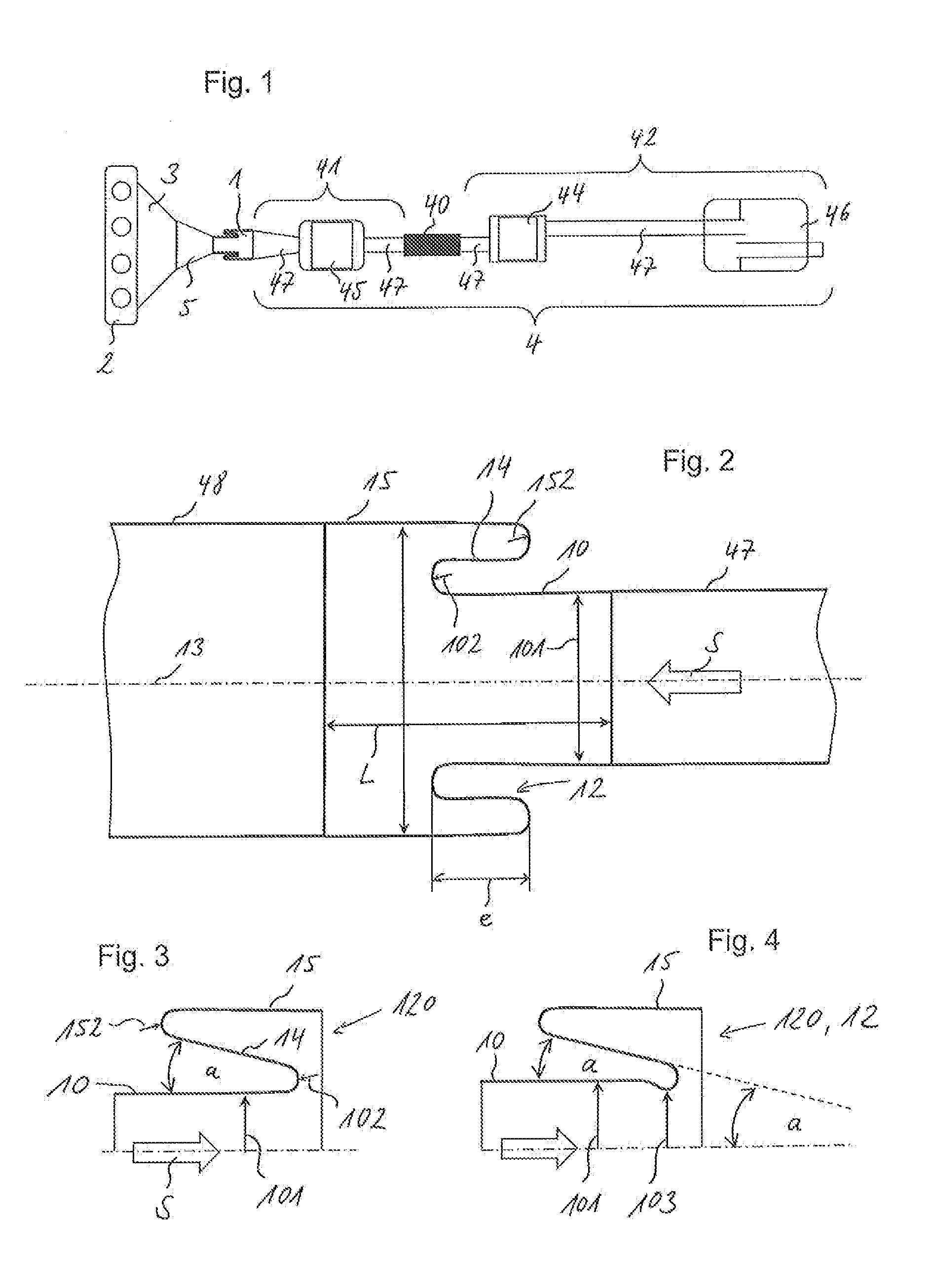
[0032]FIG. 1 shows an exhaust gas system 4 consisting of a first section 41 and a second section 42. The first section 41 is formed by a converter 45 and exhaust gas pipes 47 connected on both sides of converter 45. The second section 42 consists of a particulate filter 44 and a muffler 46, with the particulate filter 44 and the muffler 46 being interconnected via an exhaust gas pipe 47. Upstream of the particulate filter 44 there is also provided an exhaust gas pipe 47 to which a mechanical de-coupling element 40 is connected which interconnects the two sections 41, 42. The purpose of the mechanical de-coupling element 40 is essentially to guarantee a certain freedom of movement of the exhaust gas system 4 over its entire length.

[0033]The entire exhaust gas system 4 is connected via a sound-absorbing insulating element 1 to an outlet opening of a turbocharger 5 which connects the exhaust gas system 4 via the manifolds 3 with the internal combustion engine 2. The vibrations which ar...


PUM


Abstract

An exhaust system composed of a plurality of components for an internal combustion engine for connecting to a manifold, the exhaust system includes at least one, first section, which is provided indirectly or directly after the manifold in the flow direction, arid a second section, which is directly adjacent thereto in the flow direction, wherein the two sections are connected to each other by a mechanical decoupling element. The resonant oscillations in the range above 600 Hz are to be attenuated in the exhaust system by more than 15 dB and, at the same time, the exhaust system is to be sufficiently rigid and self-supporting and designed to be lastingly gas-tight. For this purpose, a single-walled arid self-supporting acoustic insulating element is integrated in the exhaust system in the flow direction upstream of, or in, the first section.

Description

FIELD OF THE INVENTION[0001]The invention relates to an exhaust gas system for an internal combustion engine to be connected to a manifold. The exhaust gas system consists of at least one first section provided in the direction of flow directly or indirectly downstream of the manifold, and of a second section following it in the direction of flow with the two sections being interconnected via a mechanical de-coupling element.BACKGROUND OF THE INVENTION[0002]The exhaust gas system Is mechanically de-coupled by means of the de-coupling element for providing a certain degree of flexibility over the length of the vehicle. As mechanical de-coupling elements non-self-supporting, flexible connecting elements, such as corrugated tubes or flexible, tubes are, inserted between two sections of the exhaust gas system. Due to the fact that the corrugated tubes or flexible tubes are hot self-supporting, they must be supported. Owing to their small degree of stiffness and flexibility, they have al...

Claims


Application Information

Patent Timeline
Patent Type & Authority Applications(United States)
IPC IPC(8): F02K1/82
CPCF01N13/08F01N2260/10F01N13/1816
Inventor PFEFFER, TOBIASFUHRMANN, BERND
Owner TENNECO GMBH
Why Eureka
Try Eureka