Pin assembly for a two-part ground engaging tooth system and method for connecting components of a two-part ground engaging tooth system to each other

a two-part, ground-engaged technology, applied in the direction of soil-shifting machines/dredgers, couplings, mechanical equipment, etc., can solve the problems of affecting the repair/replacement of the replacement part, the cutting edge of the replacement part sometimes quickly wears and dulls, and the component parts of the digging tooth assembly experience considerable and rapid wear, etc., to achieve the effect of enhancing the ease of repair/replacement and adding structural rigidity to the pin

Inactive Publication Date: 2006-03-23
H & L TOOTH
View PDF23 Cites 23 Cited by
  • Summary
  • Abstract
  • Description
  • Claims
  • Application Information

AI Technical Summary

Benefits of technology

[0025] According to still another aspect, there is provided a method for releasably securing a ground engaging tool on a nose portion of a mounting support by extending through spaced and substantially aligned first and second openings defined by the tool and a bore defined by the nose portion of said support. The method comprises the steps of: inserting a first member into a lengthwise section of the bore in the nose portion of the support through the first opening defined by the tool, with the first member including a head portion and a shank portion, with the head portion of the first member being configured to engage with a marginal portion of the respective opening in the tool through which that member is inserted, and with the shank portion of the first member being configured to engage with a marginal portion of the bore defined by the nose portion of the adapter; inserting a second member into a lengthwise section of the bore in the nose portion of the support through the other opening defined by the tool, with the second member including a head portion and a shank portion, with the head portion of the second member being configured to engage with a marginal portion of the respective opening in the tool through which the second member is inserted, and with a free end of the shank portion of the second member being configured to be arranged in a cooperative relation relative to the free end of the shank portion of the

Problems solved by technology

In some digging operations, such teeth assemblies are subjected to highly abrasive conditions and, thus, experience considerable and rapid wear.
Unless the conjuncture between the component parts of the two-part system is properly fitted, wear problems, especially in the pocket or cavity of the replacement part and along the nose portion of the adapter, can result.
Moreover, the relatively high forces developed during some digging operations furthermore add to the rapid wear of the component parts of the digging tooth assembly.
In service, and although specific steps can be taken during fabrication of the digging teeth to prolong the usefulness thereof, a forward cutting edge of the replacement part sometimes quickly wears and become dull and, thus, inefficiencies in the digging operation develop thereby requiring replacement of such parts.
Removing or separating a worn or otherwise broken tool from its support, however, can involve a tedious and often difficult task of pounding the retaining pin from registering apertures in component parts of the two-piece assembly.
Of course, with larger two-part digging systems, the retaining pins are proportionately sized larger thereby adding to the manual effort and, thus, increasing the time and effort involved to effect digging tooth replacement and/or repair.
Problems involving the hammer missing the punch or other tool used to removably pound the retaining pin and hitting the hand of the operator are well known.
Of course, similar problems exist when the retaining pin is again pounded into the apertures to effect reattachment of the replacement part

Method used


Image

  • Pin assembly for a two-part ground engaging tooth system and method for connecting components of a two-part ground engaging tooth system to each other
  • Pin assembly for a two-part ground engaging tooth system and method for connecting components of a two-part ground engaging tooth system to each other
  • Pin assembly for a two-part ground engaging tooth system and method for connecting components of a two-part ground engaging tooth system to each other

Examples


Embodiment Construction

[0049] While the present invention is susceptible of embodiment in multiple forms, there are shown in the drawings and will hereinafter be described various preferred embodiments of the present invention with the understanding the present disclosure is to be considered as setting forth exemplifications of the invention which are not intended to limit the invention to the specific embodiments illustrated and described.

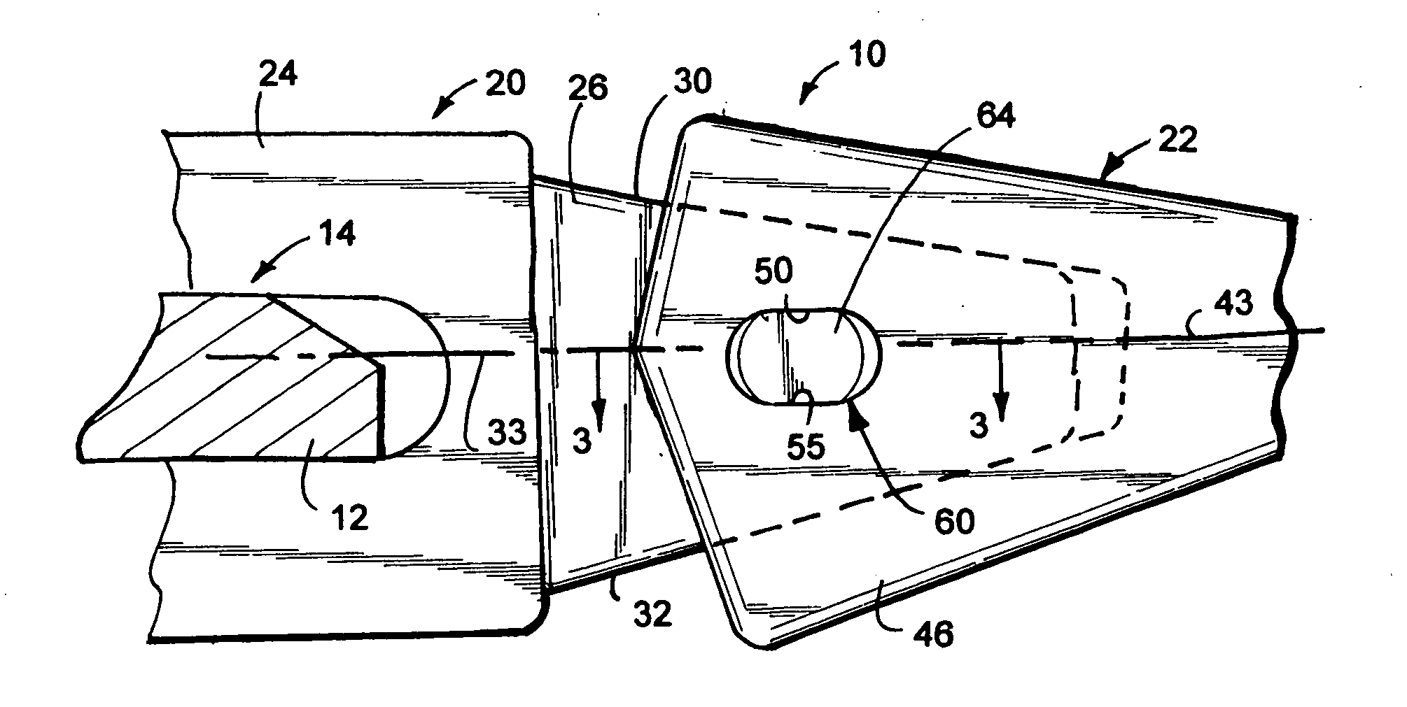
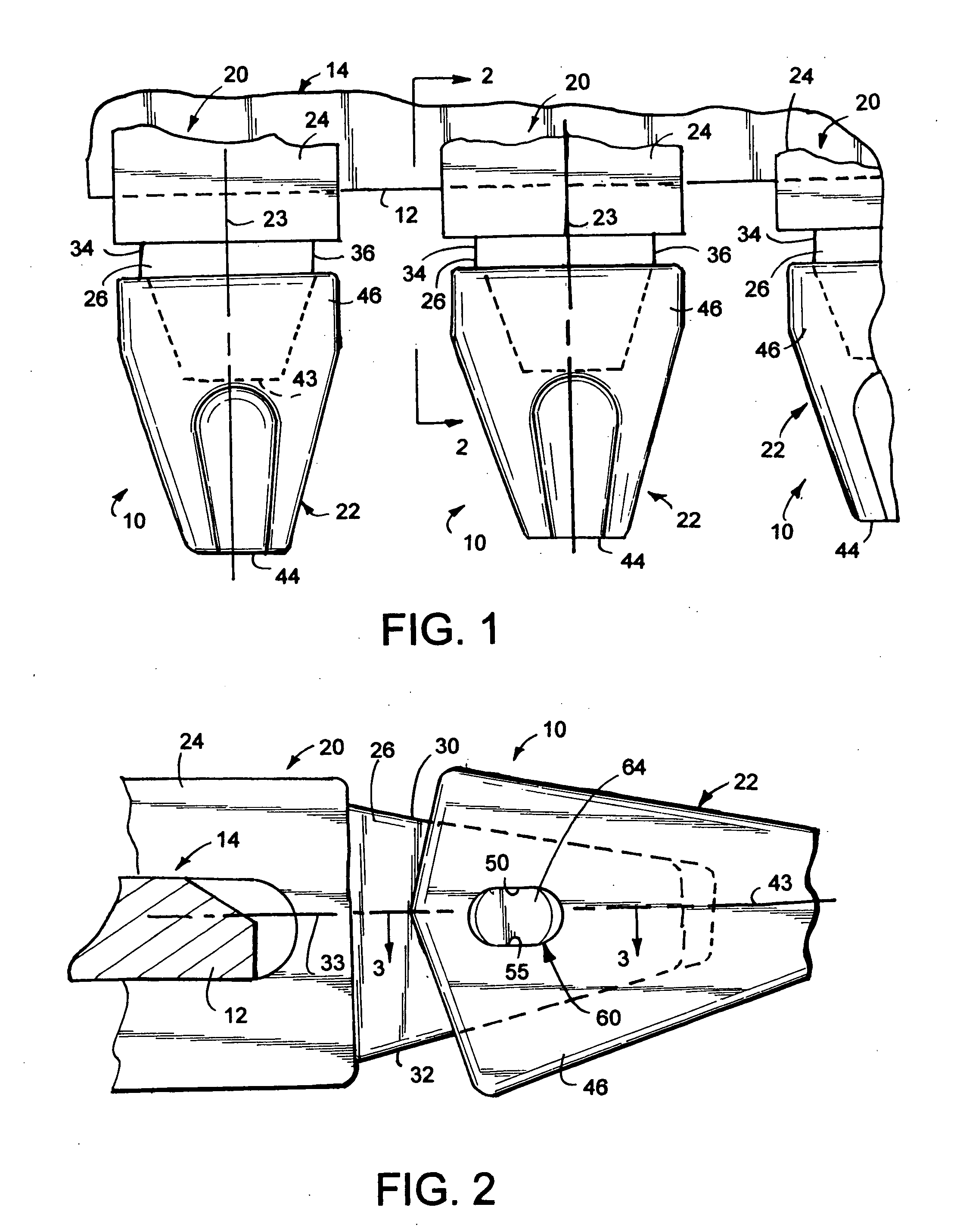
[0050] Referring now to the drawings, wherein like reference numerals indicate like parts throughout the several views, there is shown in FIG. 1 a series of two-part digging assemblies, with each assembly being identified generally by reference numeral 10. As is typical, the two-part assemblies are arranged in horizontally proximate relation relative to each other across a forward edge or lip 12 of a ground engaging implement such as a bucket or the like 14. It should be appreciated that during operation, the bucket or shovel 14, to which the two-part system 10 is atta...


PUM


Abstract

A pin assembly for releasably maintaining an adapter and replaceable part or tool of a two-part digging system in operable combination relative to each other. The pin assembly includes a pair of axially aligned retaining pins whose opposed ends are arranged in operable combination relative to each other. Each retaining pin has an enlarged head portion configured to fit within one of the openings defined by the tool, and a shank portion. An axially arranged and rotatable fastener maintains the opposed distal ends of the pins in releasably secured relation relative to each other. A method for releasably maintaining the digging tooth/tool and adapter is operable combination is also disclosed.

Description

CROSS REFERENCE TO RELATED APPLICATIONS [0001] This application claims the benefit of prior U.S. provisional application Ser. No. 60 / 610,798, filed Sep. 17, 2004, and entitled “HAMMERLESS PIN ASSEMBLY FOR A TWO-PART GROUND ENGAGING TOOTH SYSTEM”.FIELD OF THE INVENTION [0002] The present invention generally relates to a two-part ground engaging tooth system and, more specifically, to a pin assembly for maintaining an adapter and a replacement part of a two-part ground engaging tooth system in operable combination relative to each other and to a method for connecting component parts of a two-piece ground engaging tooth system to each other. BACKGROUND OF THE INVENTION [0003] Excavating equipment used in mining, construction and a myriad of other ground engaging operations typically includes a series of spaced apart ground engaging tools which project forward and serve to break up material to be gathered into a bucket of such excavating equipment. To enhance the ability of such ground ...

Claims


Application Information

Patent Timeline
IPC IPC(8): E02F9/28
CPCY10T403/45E02F9/2833
Inventor CLENDENNING, CHARLESLAUNDER, BRIAN L.
Owner H & L TOOTH
Why Eureka
Try Eureka