

Exhaust gas turbocharger with integration of bearing components
- Summary
- Abstract
- Description
- Claims
- Application Information
AI Technical Summary
Benefits of technology
Problems solved by technology
Method used
Image

Examples
Embodiment Construction
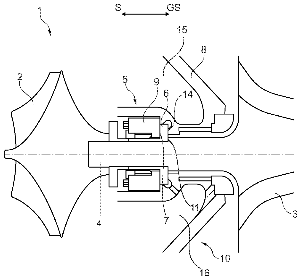
[0016]In the FIGURE, a sectional view of an exhaust gas turbocharger 1 having a compressor wheel 2, a turbine 3 and a shaft 4, which rotatably interconnects the compressor wheel 2 and the turbine 3, is shown. On the shaft 4 a thrust ring 6, preferentially a one-piece thrust ring 6, is arranged, which indirectly connects the shaft 4 with the bearing 5 and is configured to transmit the axial forces acting on the shaft 4 both in a thrust direction S and also in the counter-thrust direction GS opposite to the thrust direction. The thrust ring 6 is hollow-cylindrically and non-positively arranged on the shaft 4. Furthermore, the thrust ring 6, at an end facing to the turbine 3, extends at a right angle to the outside such that the sectional view is L-shaped. Through this extent, the thrust ring 6 has a thrust surface 7 and a counter-thrust surface 14. For absorbing the axial force in the thrust direction S, the thrust surface 7 lies against the bearing 5 such that axial forces in the dir...
PUM
 Abstract
Description
Claims
Application Information