
Gas-liquid separator

Active Publication Date: 2018-12-20
USUI KOKUSAI SANGYO KAISHA LTD
View PDF41 Cites 8 Cited by
  • Summary
  • Abstract
  • Description
  • Claims
  • Application Information

AI Technical Summary

Benefits of technology

The patent aims to improve the performance of separating gas from liquid in a swirl flow generator. The invention also aims to reduce the space required for installation.

Problems solved by technology

As a result, the separation performance of the liquid deteriorates.
Further, in the case of the double pipe structure where the downstream portion of the first pipe is inserted into the second pipe which has larger diameter, an installation space required for the gas-liquid separator is relatively large, which makes it difficult to install the gas-liquid separator in a limited space of an exhaust pipe of the internal combustion engine, for example.

Method used


Image

  • Gas-liquid separator
  • Gas-liquid separator
  • Gas-liquid separator

Examples


first embodiment

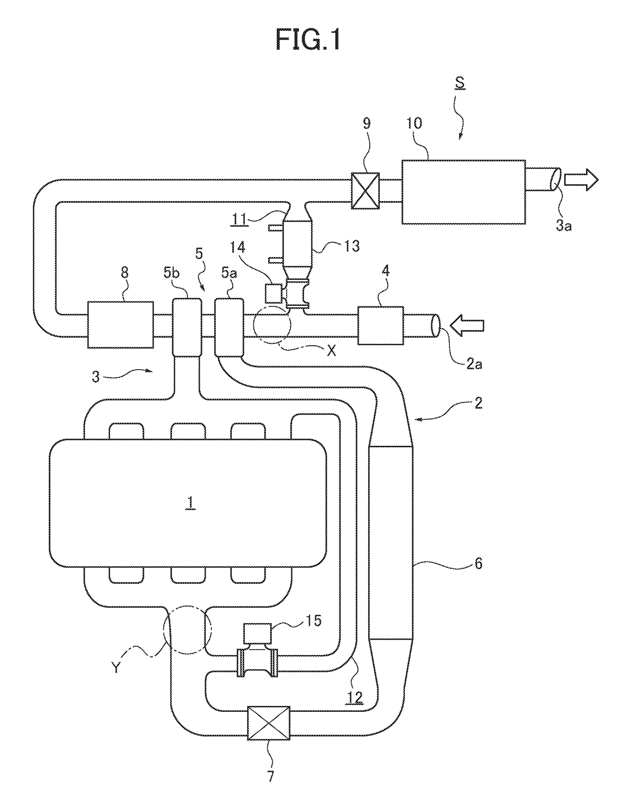
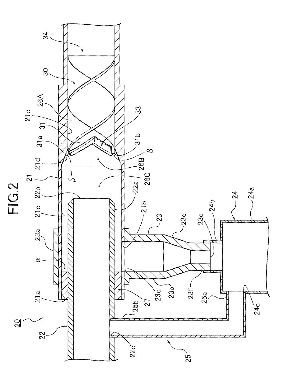
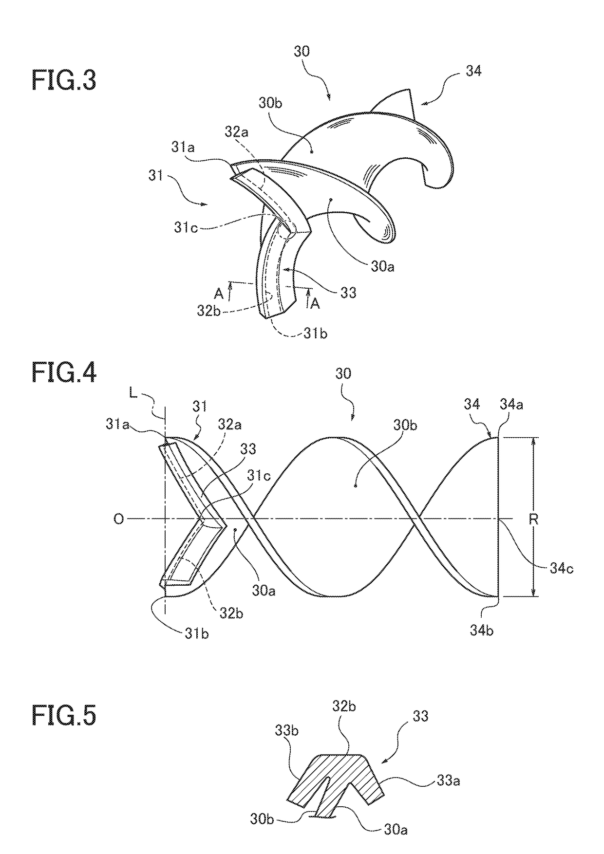
[0030](First Embodiment) First, the configuration of a gas-liquid separator 20 in the First Embodiment will be separately described under headings “Overall Configuration of System”, “Detailed Configuration of Gas-Liquid Separator”, and “Detailed Configuration of Swirling Flow Generating Ribbon”.

[0031](Overall Configuration of System) FIG. 1 is an entire system diagram illustrating an exhaust gas recirculation system of an internal combustion engine to which a gas-liquid separator according to the First Embodiment is applied.

[0032]Hereinafter, an overall configuration of the system in the First Embodiment will be described with reference to FIG. 1.

[0033]The gas-liquid separator 20 in the First Embodiment is applied to an exhaust gas recirculation system S of an internal combustion engine 1 shown in FIG. 1. Here, the internal combustion engine 1 shown in FIG. 1 is a diesel engine mounted in a vehicle as a driving source for traveling, and includes four cylinders (not shown). Each of t...

second embodiment

[0086](Second Embodiment) In a gas-liquid separator an inlet pipe includes an upstream drain port and a pipe cooling structure or pipe cooler. An inner pipe includes a circular groove, a protrusion and a heater, and a swirling flow generating ribbon includes a ribbon cooling structure or ribbon cooler.

[0087]First, the configuration of a gas-liquid separator will be described. FIG. 8 is a cross sectional view illustrating a gas-liquid separator according to the Second Embodiment. Hereinafter, the configuration of a gas-liquid separator 40 according to the Second Embodiment will be described with reference to FIG. 8.

[0088]As shown in FIG. 8, the gas-liquid separator 40 according to the Second Embodiment includes an inlet pipe 41, an inner pipe 42, a first drainpipe 43, a reservoir tank 44, a second drainpipe 48, and a swirling flow generating ribbon 50.

[0089]The inlet pipe 41 is in communication with an intake port (not shown) and a low-pressure EGR valve (not shown) at an upstream e...


PUM

PropertyMeasurementUnit
Flow rateaaaaaaaaaa
Diameteraaaaaaaaaa

Abstract

A gas-liquid separator includes the inlet pipe and an inner pipe. The inlet pipe receives a swirling flow generating ribbon, and includes an exhaust port through which a separated gas flows out and a drain port through which a separated liquid flows out. The outer diameter of the inner pipe is smaller than the inner diameter of the inlet pipe. An end of the inner pipe is inserted into the exhaust port and is open at a location downstream of the swirling flow generating ribbon. A terminal end of the swirling flow generating ribbon (30) includes a first terminal edge and a second terminal edge. The first and second terminal edges connect a first terminal end point, a second terminal end point, and a middle terminal end point.

Description

CROSS-REFERENCE TO RELATED APPLICATION[0001]This application is based upon and claims the benefit of priority from Japanese Patent Application No. 2015-246468 filed on Dec. 17, 2015, the entire disclosure of which is incorporated herein by reference.TECHNICAL FIELD[0002]The present disclosure generally relates to a gas-liquid separator and more specifically to a gas-liquid separator that swirls a gas-liquid two-phase fluid flowing through a pipe by a swirling flow generating ribbon and guides liquid to an inner surface of the pipe by centrifugal force.BACKGROUND ART[0003]Conventionally, a gas-liquid separator that swirls a gas-liquid two-phase fluid flowing through a pipe by a swirling flow generating ribbon and guides liquid to an inner surface of the pipe by centrifugal force is known (see Patent Literature 1: JP 2003-62416A, for example). The swirling flow generating ribbon is formed from a helically twisted plate member. Further, a gas-liquid separator having a double pipe struc...

Claims


Application Information

Patent Timeline
IPC IPC(8): B01D45/16F02M35/022
CPCB01D45/16F02M35/0223F02M26/06F02M26/05F02M26/22B04C3/02B04C3/06B04C2003/006B01D45/12F02M35/10F02M26/50Y02T10/12
Inventor SUZUKI, TETSUNOBUITO, HIDETAKASERIZAWA, YOSHIYUKI
Owner USUI KOKUSAI SANGYO KAISHA LTD
Learn More