
Vortex finder for a cyclonic separator

Active Publication Date: 2017-01-12
KONINKLJIJKE PHILIPS NV
View PDF2 Cites 7 Cited by
  • Summary
  • Abstract
  • Description
  • Claims
  • Application Information

AI Technical Summary

Benefits of technology

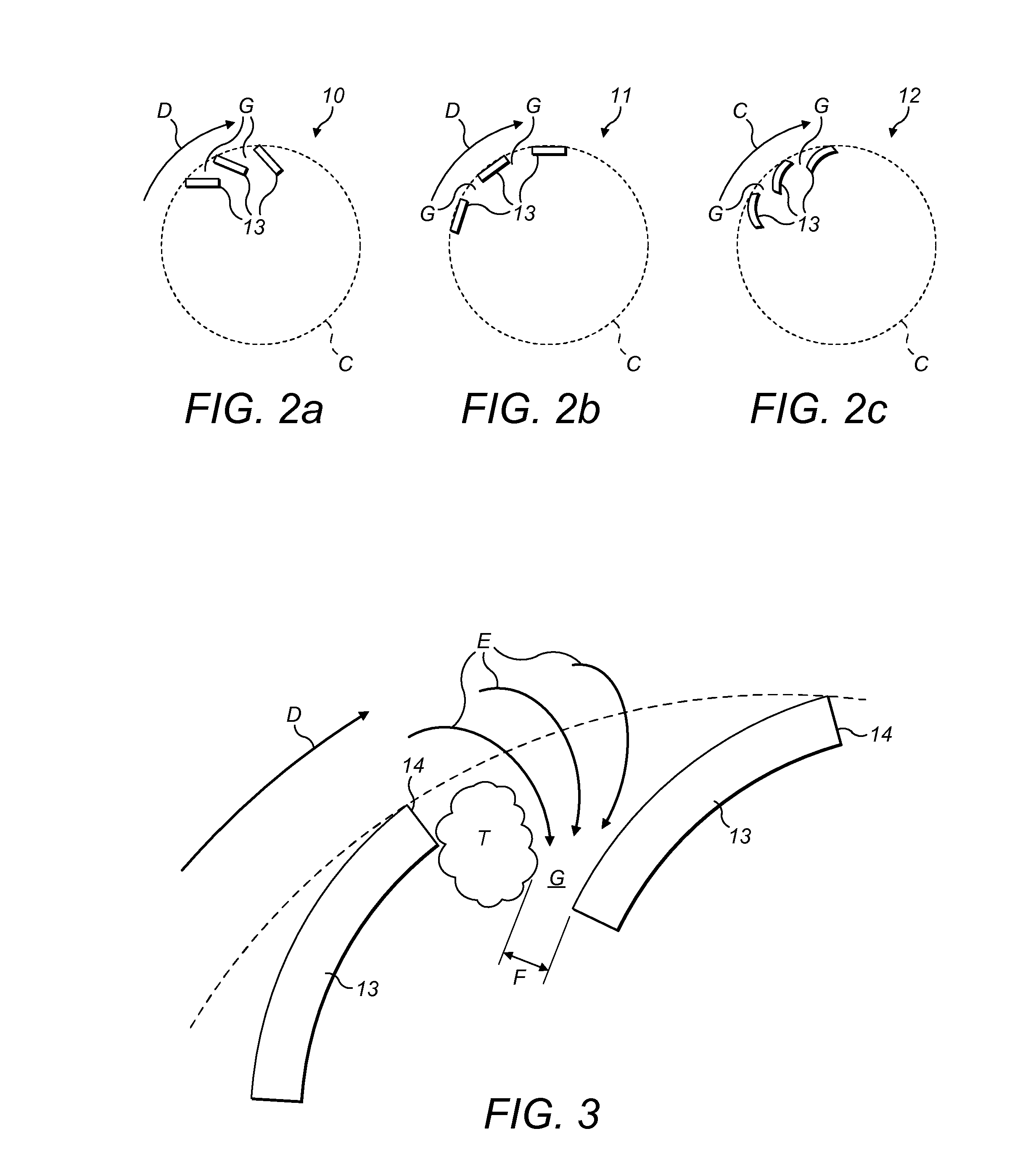
The present invention provides a vortex finder for a cyclonic separator that reduces pressure drop to increase air flow while improving separation performance. The invention includes a plurality of stationary vanes positioned radially around the cyclone chamber's axis, with the vanes spaced apart from each other. The vanes redirect air flow around them and through gaps between them, creating a region of overpressure that minimizes turbulence and improves the separation process. The angle between the first plane that extends at a tangent to the outer surface of a vane and a second plane that extends at a tangent to the outer surface of an adjacent vane at a point where the first tangent line intersects the adjacent vane is important and should be greater than 15 degrees. A more preferred angle is between -30 degrees and -60 degrees.

Problems solved by technology

In particular, a vortex finder prevents turbulence in the vicinity of the outlet causing excessive noise, loss of pressure, and reduction of the collection efficiency of the separator.

Method used


Image

  • Vortex finder for a cyclonic separator
  • Vortex finder for a cyclonic separator
  • Vortex finder for a cyclonic separator

Examples


Embodiment Construction

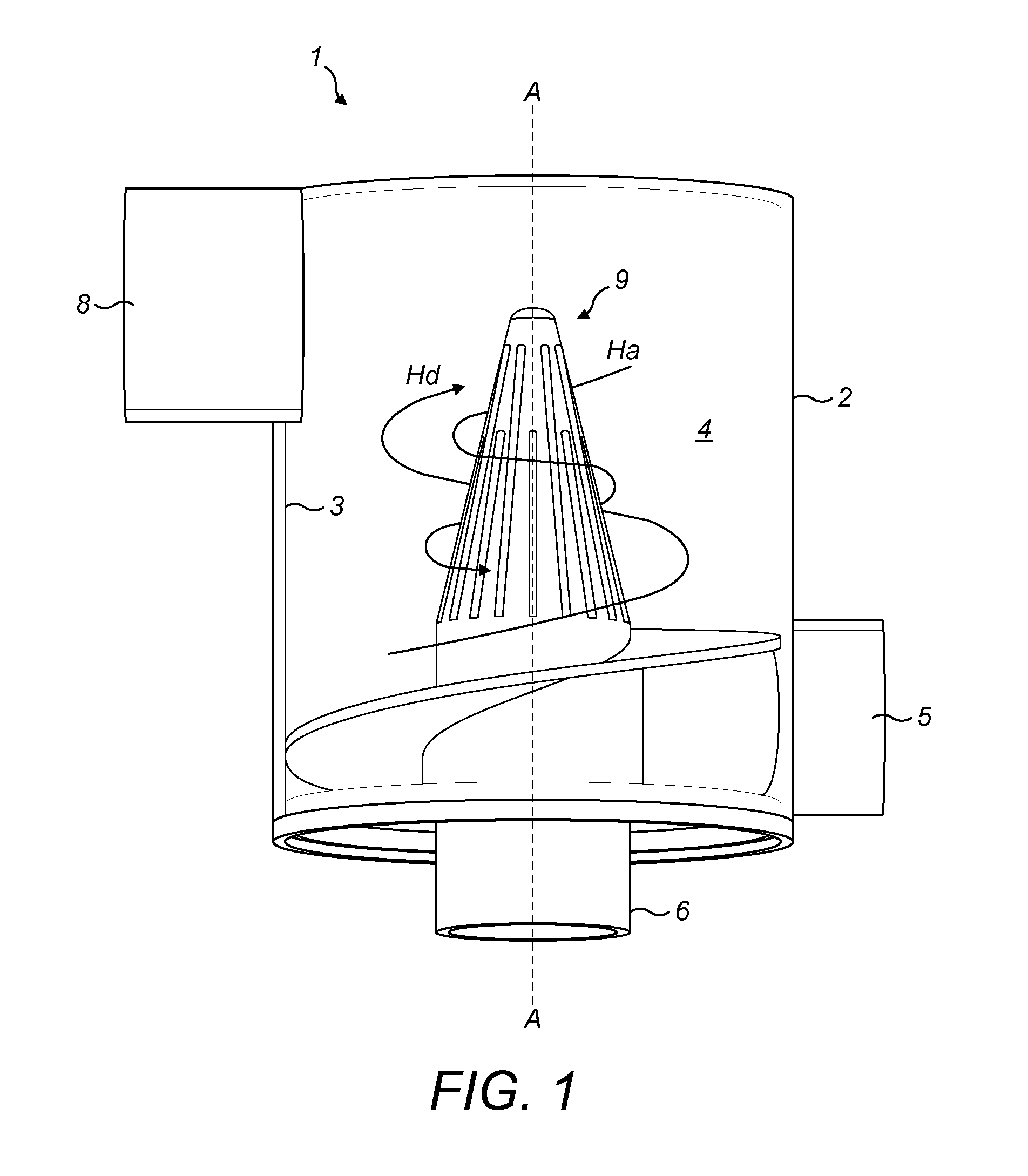
[0033]Referring now to FIGS. 1 to 3, a known cyclonic separator 1 that may be used for a bagless-type vacuum cleaner is shown. The cyclonic separator 1 comprises a cyclone housing 2.

[0034]The cyclone housing 2 has an inner peripheral wall surface 3 that defines a cyclone chamber 4, a tangentially positioned debris-laden air inlet 5 and an axially positioned clean air outlet 6. The cyclone chamber 4 has a longitudinal axis denoted by line ‘A-A’. A tangentially positioned debris laden air outlet 8 is provided at the opposite end of the chamber 4 to the debris inlet 5, which leads to a debris collection chamber (not shown).

[0035]The inlet 5 is angled tangentially to the central axis A-A of the cyclone chamber 4 such that air and entrained debris drawn into the cyclone chamber 4 through the inlet 5 will flow in a helical or swirling path Hd towards the outlet 8. Debris entrained in the airflow is directed outwardly under centrifugal force and passes through the outlet 8 and into the deb...


PUM

PropertyMeasurementUnit
Angleaaaaaaaaaa
Shapeaaaaaaaaaa
Radiusaaaaaaaaaa

Abstract

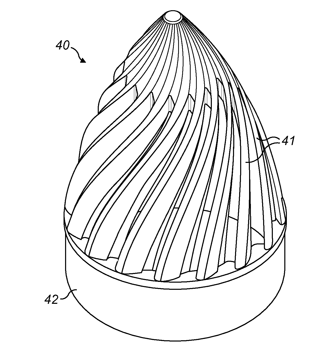
A vortex finder (18,27,40) for a cyclonic separator (1) through which air flowing in a helical path ‘D’ about an axis A-A of a cyclone chamber (4) passes to an outlet (6) is disclosed. The vortex finder comprises a plurality of stationary overlapping vanes (13,19) extending in an axial direction and spaced radially around said axis‘A’, the vanes (13,19) being positioned relative to each other so a helical flow of air about the axis of the cyclone chamber (4) passes over an outer surface (16) of the vanes (13,19) with a portion of the air flow being redirected around a leading edge (14) of each vane (13,19) and through a gap between adjacent vanes (13,19) to the outlet (6). At any point along the axis, a portion of an outer surface (16,20,30,46) of each vane (13,19,28,41) lies on a circle having its center coaxial with said axis, the outer surface (16,20,30,46) of each vane (13,19,28,41) having a portion leading towards the leading edge (14,33,47) that extends inwardly away from the circle so that the leading edge (14,33,47) of each vane (13,19,28,41) about which air is redirected through the gap between vanes (13,19,28,41) is located within a region bound by said circle to create a region of overpressure on the outer surface (16) of the adjacent vane (13,19) in the vicinity of the gap.

Description

FIELD OF THE INVENTION[0001]The present invention relates to a vortex finder for a cyclonic separator and to a cyclonic separator comprising a vortex finder according to the invention. The invention also relates to a vacuum cleaner comprising the vortex finder and / or a cyclonic separator according to the invention.BACKGROUND OF THE INVENTION[0002]Cyclonic separators rely on rotational effects to separate solids entrained in a fluid flow without using a filter. Cyclone separators are commonly used to separate dust and debris from the suction airflow of vacuum cleaners. Known cyclonic separators comprise a cylindrical or conical cyclone chamber with an air inlet and an air outlet. The air inlet is angled obliquely to the central axis of the cyclone chamber so that when debris laden air enters the cyclone chamber via the inlet, a rapidly rotating flowing air flow or vortex is established within the cyclone chamber. The air enters the cyclone chamber via an inlet and flows towards the o...

Claims


Application Information

Patent Timeline
IPC IPC(8): B04C5/13A47L9/16
CPCB04C5/13B04C2005/136A47L9/1666A47L9/1608A47L9/1683A47L9/1641B01D50/20
Inventor VAN WOLFEREN, PAULUS HERMANUSVAN DER KOOI, JOHANNES TSEARDDUINEVELD, PAULUS CORNELIS
Owner KONINKLJIJKE PHILIPS NV
Learn More