Fluid heater

a heater and flue technology, applied in water heaters, combined heat and power systems, lighting and heating apparatus, etc., can solve problems such as shortcoming detracting from their usefulness, damage to the heating assembly itself or other subassemblies, and overheating of the internal combustion engine, so as to facilitate the heating and maintenance of the source

Inactive Publication Date: 2012-06-28
HOTSTART
View PDF0 Cites 20 Cited by
  • Summary
  • Abstract
  • Description
  • Claims
  • Application Information

AI Technical Summary

Benefits of technology

[0006]Another aspect of the present invention relates to a fluid heater which includes an object of interest which, in operation, has a predetermined operational temperature range, and a maximum operational temperature; a source of fluid which is utilized within the object of interest, and which facilitates, at least in part, the maintenance of the operational temperature of the object of interest; a pump, having a pump motor, and which is coupled in fluid flowing relation relative to the object of interest, and which, when energized, removes and then returns the source of fluid to the object of interest; a heater which is positioned in downstream fluid receiving relation relative to the pump, and pump motor, and which is further located in upstream fluid delivering relation relative to the object of interest, and wherein the heater, when energized, imparts heat energy to the fluid which is supplied to the heater by the pump; a first temperature sensor positioned in upstream, fluid flowing relation relative to the heater, and wherein the first temperature sensor detects the temperature of the fluid which is received from the object of interest; a second temperature sensor positioned in downstream, fluid flowing relation relative to the heater, and which is further positioned upstream relative to the object of interest, and wherein the second temperature sensor detects the temperature of the source of fluid as the source of fluid leaves the heater, and travels back to the object of interest; a first temperature controlled relay which is electrically coupled to the first temperature sensor and which, when electrically closed, is effective in energ

Problems solved by technology

While earlier heater designs employed for the purposes, noted above, have worked with varying degrees of success, there have been shortcomings which have detracted from their usefulness.
Further, and under

Method used


Image

  • Fluid heater
  • Fluid heater
  • Fluid heater

Examples


Embodiment Construction

[0016]This disclosure of the invention is submitted in furtherance of the constitutional purposes of the U.S. Patent Laws “to promote the progress of science and useful arts” (Article 1, Section 8).

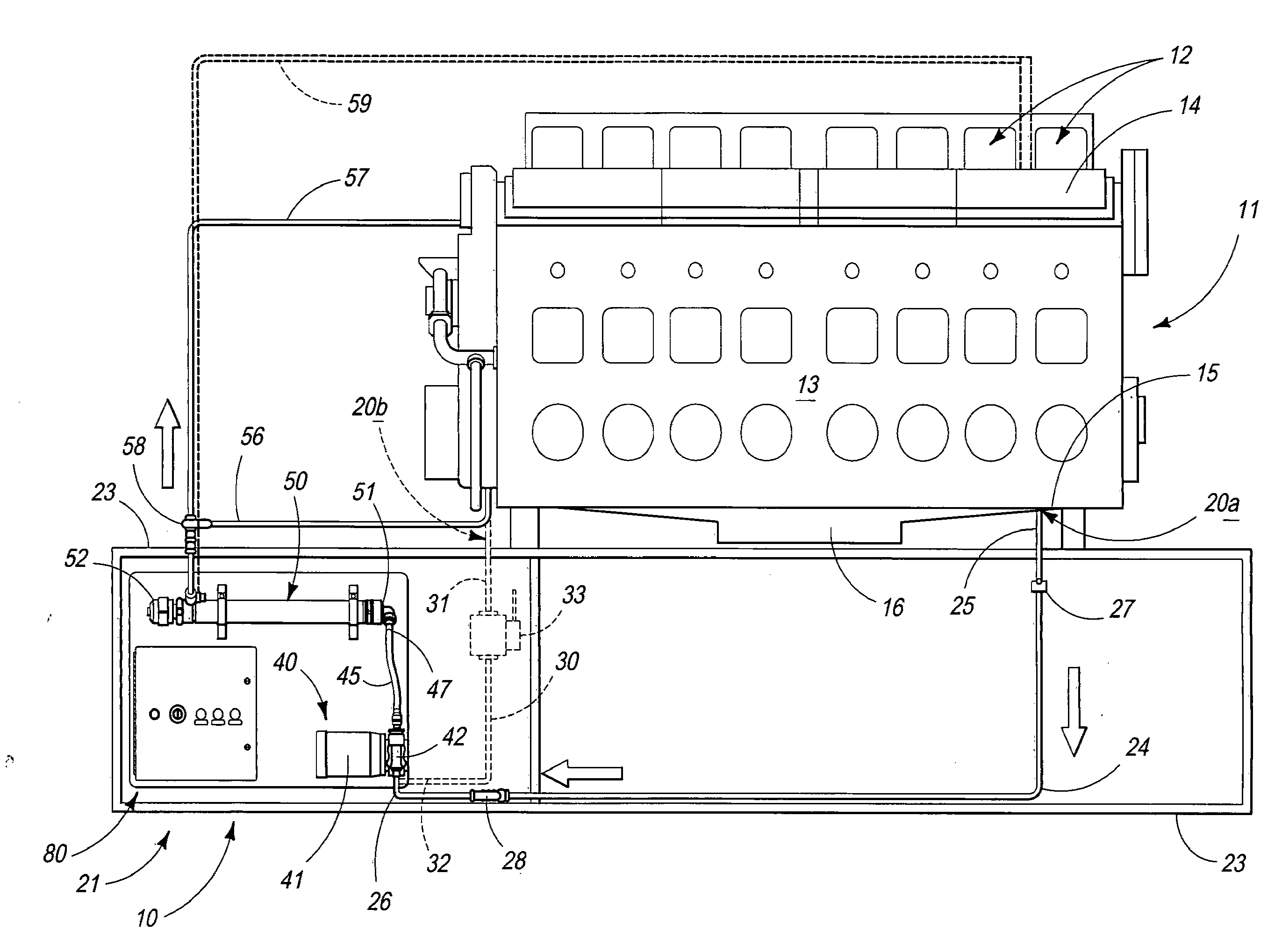
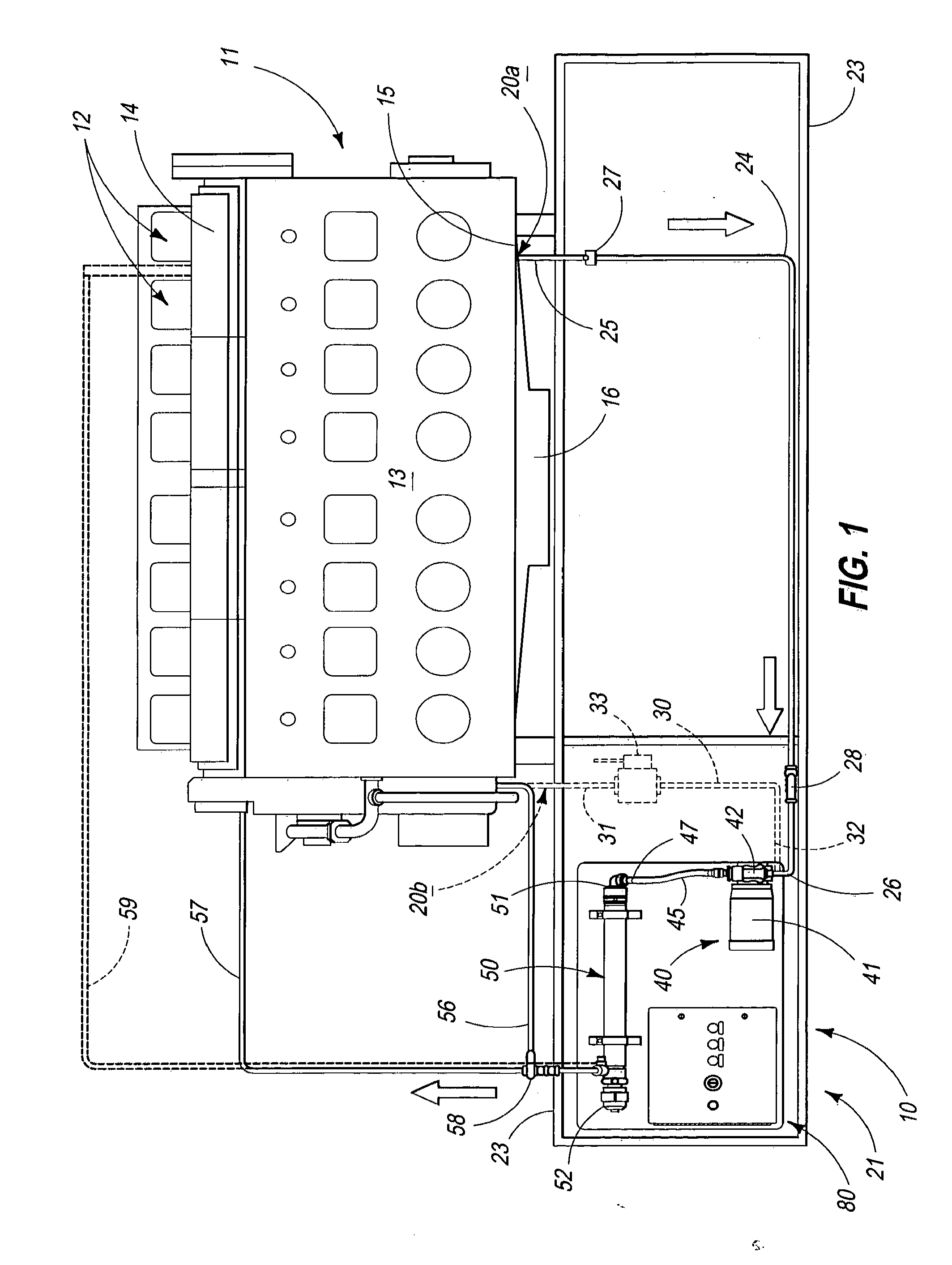
[0017]Referring more particularly to the drawings, the fluid heater 10 of the present invention is best understood, in its broadest aspect, by a study of FIG. 1. As seen therein, the invention 10 relates to a fluid heater which is operably coupled in fluid flowing relation relative to an object of interest, here depicted as internal combustion motor or engine of conventional design and which is designated by the numeral 11. The internal combustion motor or engine 11, as illustrated, is a diesel-type motor or engine which has a multiplicity of cylinders 12 which are made integral with an engine block 13 of conventional design. The engine block has a top portion 14, and a bottom portion 15. An oil sump 16 is made integral with the bottom portion 15. As will be discussed hereinafter, the flu...


PUM


Abstract

A fluid heater is disclosed and which has a heater, pump, and a plurality of temperature sensors which are electrically coupled with first and second temperature controlled relays, and wherein the fluid heater is operable to maintain a source of fluid used by an object of interest within a predetermined temperature range and further, is operable under given temperature conditions to discontinue operation so as to protect the object of interest and the heater from becoming damaged through overheating of the fluid which is utilized by same.

Description

TECHNICAL FIELD[0001]This invention relates to a fluid heater having particular utility when used with an internal combustion engine or motor, and more specifically to a fluid heater which maintains the temperature of a source of fluid utilized by an internal combustion engine or motor at an appropriate temperature so as to facilitate the operation of same.BACKGROUND OF THE INVENTION[0002]The beneficial effects of employing various types of heater assemblies for maintaining the temperature of a source of fluid such as a lubricant or coolant and which is supplied to an internal combustion engine is well known. Various block heaters, of assorted designs, have been utilized with internal combustion motors which are used on assorted overland vehicles, such as locomotives, diesel operated trucks and automobiles in order to allow such vehicles to effectively operate during extremely cold temperatures. In some non-mobile applications, diesel motors are employed to drive sub-assemblies such...

Claims


Application Information

Patent Timeline
IPC IPC(8): F24H1/08H05B1/02F24D18/00
CPCF24H1/102F24H9/2028F24H1/101F24H2240/06F24H2250/02F24D2101/70F24D18/00F24H15/175F24H15/219F24H15/395F24H15/215F24H15/124F24H15/37
Inventor SEDLACEK, DAVID R.ABBOTT, MICHAEL T.MCFARLAND, CHRISTOPHER M.
Owner HOTSTART
Why Eureka
Try Eureka