Image forming apparatus and heating method for fixation section of the same

a technology of image forming apparatus and heating method, which is applied in the direction of electrographic process apparatus, instruments, optics, etc., can solve the problems of not being disclosed, and achieve the effect of reducing the maximum power consumption of the image forming apparatus

Active Publication Date: 2012-06-28
BROTHER KOGYO KK
View PDF2 Cites 10 Cited by
  • Summary
  • Abstract
  • Description
  • Claims
  • Application Information

AI Technical Summary

Benefits of technology

[0025]In the above case, because the roller is only rotated under the second control, it is possible to reduce the maximum power consumption when operat

Problems solved by technology

Further, the aforementioned document does not disclose as to whether or not the heating mechanism can be changed to an ener

Method used


Image

  • Image forming apparatus and heating method for fixation section of the same
  • Image forming apparatus and heating method for fixation section of the same
  • Image forming apparatus and heating method for fixation section of the same

Examples


Embodiment Construction

[0031]Next, with reference to FIGS. 1 to 5, a preferred embodiment of the present teaching will be explained.

1. Overall Configuration of the Printer

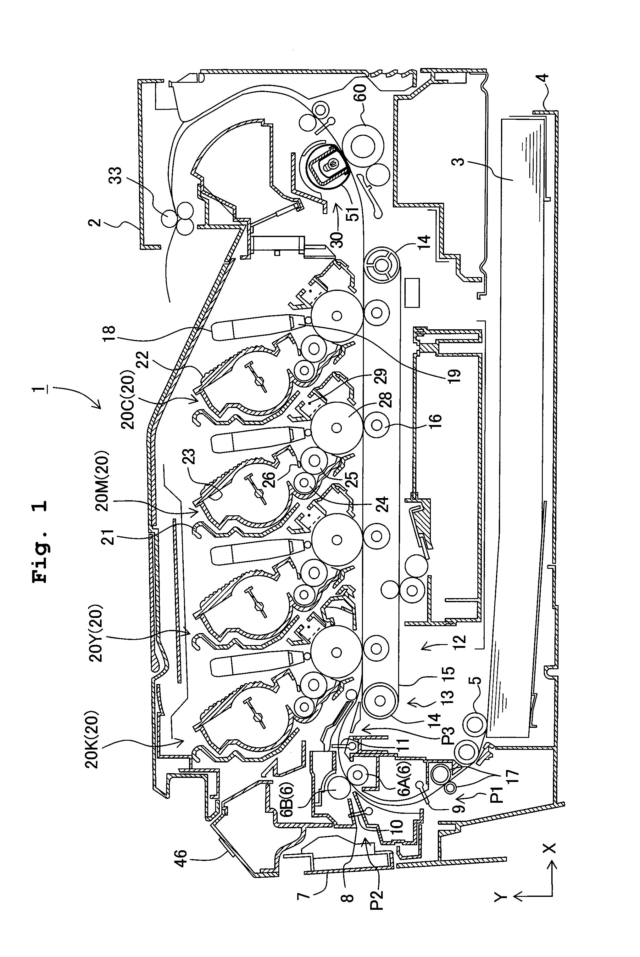
[0032]A printer 1 is a color LED printer of a direct tandem type utilizing four-color (black K, yellow Y, magenta M, and cyan C) toners to form color images. In the following explanations, the left side in a horizontal direction (an X-axis direction) in FIG. 1 is defined as the front side. Further, in FIG. 1, with respect to the same or equivalent constitutive parts or components for the different colors, reference numerals will be omitted as appropriate. Further, the image forming apparatus is not limited to a color LED printer of a direct tandem type, but may as well be a color laser printer, a monochrome laser printer, or a multifunction printer with a photocopy function and the like.

[0033]The printer 1 includes a body casing 2, and a paper feed tray 4 capable of accommodating a plurality of sheets of printing paper 3 (an example of t...


PUM


Abstract

An image forming apparatus includes: an image forming section; a fixation section having a heating mechanism and a roller arranged to face the heating mechanism; a temperature detector for detecting temperature of the fixation section; and a controller for performing a first heating-control in a first heating mode to raise the temperature of the fixation section at a first changing rate, and a second heating-control in a second heating mode to change the temperature of the fixation section at a second changing rate lower than the first changing rate upon rotating the roller when the temperature of the fixation section has reached an intermediate target temperature. The controller performs the first and second heating-controls, respectively, at the time of startup of the fixation section at least once until the temperature of the fixation section reaches a final target temperature.

Description

CROSS REFERENCE TO RELATED APPLICATION[0001]The present application claims priority from Japanese Patent Application No. 2010-292085, filed on Dec. 28, 2010, the disclosure of which is incorporated herein by reference in its entirety.BACKGROUND OF THE INVENTION[0002]1. Field of the Invention[0003]The present invention relates to an image forming apparatus and, in particular, to a technique with respect to heating control at the time of startup of a fixation section of the image forming apparatus.[0004]2. Description of the Related Art[0005]Regarding an image forming apparatus, as a conventional technique for heating control at the time of startup of a fixation section, for example, the following technique is disclosed in Japanese Patent Application Laid-Open No. 2004-348036. When the initial temperature is lower than or equal to T[1] at the time of startup of a ceramic heater which is a heating mechanism of the fixation section, a controller of the image forming apparatus turns on o...

Claims


Application Information

Patent Timeline
IPC IPC(8): G03G15/20
CPCG03G15/205
Inventor OKANO, TETSUYAFUKUSADA, YUKI
Owner BROTHER KOGYO KK
Why Eureka
Try Eureka